The possibility of utilizing cuts of LiNbO3 with high piezoelectric coupling for leaky waves - 41°-YX and 49°-YX - in wideband SAW filters, has been demonstrated. The equivalent circuit model was modified for longitudinally coupled resonator filters and some second-order effects have been taken into account to improve the accuracy of filter simulation. Thick Al electrodes are used to increase the effective electromechanical coupling. Spurious SAW signals are suppressed by the frequency shift between filter cascades. Low-loss (2-3 dB) two-cascade filters with bandwidths 6-7% and high sidelobe suppression (60 dB), more typical for three-cascade filters, were designed and manufactured.
Cordless and cellular phone systems are the most rapidly growing areas of modern telecommunication. The dynamic market of compact mobile communication systems have greatly stimulated the new SAW design techniques, such as SAW coupled resonator filters [1]. The impressive results were achieved in low-loss longitudinally coupled resonator filters (LCRF) utilizing 36°-YX cut of LiTaO3 or 64°-YX cut of LiNbO3. Due to high electromechanical coupling for leaky waves propagating in these cuts (5% and 11%), the obtainable bandwidths are about 2 and 4%, respectively, which meet many RF and IF requirements for compact mobile and cellular communication systems. However, the recent tendencies of using more complicated signals and increasing the variety of service functions in these systems demand low-loss filters with wider bandwidth, up to 10%, and sufficiently high sidelobe suppression, about 60 dB.
This problem can be partially solved by complexity of filter structures and/or fabrication process[2]. But the most efficient way is to utilize the substrate with higher electromechanical coupling, for example, 41°-YX LiNbO3, having k2=17.2% or 49°-YX LiNbO3, k2=15.7% (see, for example, table 1 in [3]). The main drawback for these cuts is higher conversion of leaky SAW into bulk waves. Forexample, while the electrode thickness h/l is about0.04, the normalized value of absorption coefficient is 0.65 in 41°-YX LiNbO3 compared to 0.21 in 64°-YX LiNbO3 [4]. One more drawback is higher coupling for Rayleigh SAW, which is a spurious signal here and leads to degradation of filter selectivity to 35-40 dB. The last parameter may be improved to 50 dB by increasing the number of cascades, but in such structure insertion loss becomes higher by 0.8-1.0 dB. In addition, the obtainable bandwidth is reduced and the filter size is increased.
This paper presents the results of optimization for two-cascade resonator filters with center frequencies 400-500 MHz, fractional bandwidth 6-7% and sidelobe suppression about 60 dB, based on 41°-YX and 49°-YX cuts of LiNbO3 . The filters are smaller compared to three-cascade variant and less sensitive to technological variations in mass production.
Fig.1 shows a structure of LCRF comprising three interdigital transducers (IDTs). This structure is considered as an example. The profiles of 1st and 3rd modes which are the fundamental modes and
determine the filter performance, are also shown in Fig.1 The well known cross-field Mason-Smith equivalent circuit model has been modified for LCRF design. The model accuracy has been improved by taking into account the following second-order effects:
The filter response is simulated for arbitrary values of generator and load impedances. External circuits include matching elements and spurious coupling at the input and the output filter ports. Analytical expressions are used to account for dependencies of substrate parameters on metallization thickness and frequency, their coefficients being obtained from experimental data.
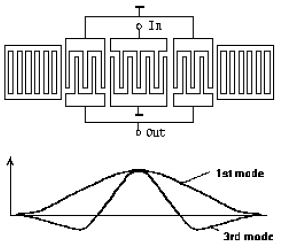
Fig. 1 The structure of resonator cascade and configuration of 1-st and 3-rd modes.
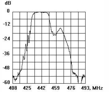
Fig.2 The experimental frequency response ½S21½ of 442 MHz resonator filter on the substrate of 64° -YX LiNbO3 . Insertion loss is 2.9 dB, fractional bandwidth is 4.3%.
Therefore, a fine tuning of the model was achieved while simulating frequency dependencies of scattering matrix coefficients S21 and S11, group delay time, input and output impedances of resonator filters (the 1st/2nd and the 1st/3rd mode configurations). 2-pole, 4-pole and 6-pole structures were analyzed consisting of arbitrary cascades. Unapodized and withdrawal weighted SAW transducers have been employed.
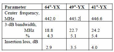
The 4-pole resonator filters having the structure shown in Fig.1 have been manufactured for comparative analysis of various LiNbO3 cuts. The number of electrodes in the middle IDT was 33 and every lateral IDT had 25 electrodes. Metallization thickness was 0.3 mm (h/l ~0.03), and the aperture width 430 mm. The frequency response of the filter with 64° -YX LiNbO3 substrate is shown in Fig.2 and the main parameters for filters based on three different cuts of LiNbO3 are presented in Table 1. It should be mentioned that these parameters were obtained using LC matching circuits (except for the 64° -YX filter).
The filters manufactured on the substrates with higher k2 have wider passbands, but greater insertion loss compared to 64° -YX cut. It is caused not only by higher propagation loss but also by the excess of
electrode number in test structures for these cuts. In order to determine the major substrate parameters as functions of metal film thickness, several filter samples were manufactured. with various thicknesses, h/l from 0.01 to 0.06.
The experimental examination of test structures and the comparison of their parameters with simulated ones enabled to calculate the values of electro-mechanical coupling and frequency behavior of reflection and absorption coefficients versus metallization thickness. In particular, for film thickness h/l=0.05-0.06 the observed effective coupling coefficient was 20-22%, that is greater by 10-15% compared to its value for h/l=0 [3]. Similar results were earlier obtained for 36° -YX cut of LiTaO3 [5].
The accurate values of electro-physical constants obtained from preliminary experimental results were further used to improve the tuning of model and to provide the better meeting of simulated and experimental results while filter design.
To evaluate the temperature behavior, filter measurements were carried out within the interval from -25 to +75 °C. The average temperature coefficients are 68 ppm/°C for both examined cuts of LiNbO3. It should be mentioned that the temperature coefficients for a LCRF are better than that of the pure substrate from [3].
The experimental response of 4-pole filter with the structure shown in Fig.1(a) is presented in Fig.3.The filter was built on 41°-YX LiNbO3 substrate. The number of electrodes in the middle IDT is 21 and each lateral IDT has 19 electrodes. All
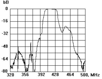
Fig.3 The experimental frequency response S21 for the 405 MHz resonator filter on the substrate of 41° -YX LiNbO3,. Insertion loss is 2.7dB, fractional bandwidth is 7.1% .
transducers are unapodized. IDT aperture width is 60l. The ratio of IDT and grating periods is 0.98. Al film thickness is 0.6 mm (h/l=0.06). Serial inductances at the input and the output are used for filter matching in 50-Ohm track. The measured filter passband is 28.8 MHz (or 7.1%) and the insertion loss is 2.8 dB. The signal suppression in stopband is more than 45 dB. Similar characteristics were obtained for 49° -YX cut. For metal film thickness 0.52 mm the measured passband was 6.4% and the insertion loss was 2.7 dB.
The typical feature of filters made on the investigated cuts of LiNbO3 is the presence of spurious resonances in the lower frequency stopband (see fig. 3). For 41° -YX LiNbO3 cut these spurious modes are somewhat higher (by 5-8 dB).
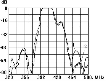
Fig.4 The simulated (1) and experimental (2) frequency responses½S21½ of the 415 MHz resonator filter with shifted periods in cascades. Substrate is 49° -YX LiNbO3, Insertion loss is 2.7, fractional bandwidth is 6.2%
The filter structures with different electrode periods in sections were investigated in order to reduce the narrowband resonance peaks. The shift in periods of two filter cascades was 0.2%. Fig.4 shows the experimental response S21 of the 415 MHz filter built on 49°-YX LiNbO3. It was found that the amplitudes of resonance peaks in the stopband are not higher than that of actual filter ripples. For comparison the simulated filter characteristic is also shown in the same figure. The agreement between the simulated and the experimental responses is very good. Somewhat higher experimental suppression in the high-frequency stopband can be explained by the frequency dependence of an absorption coefficient which increases anomalously at the frequencies higher than that of an acoustic synchronism [5].
LCRFs with apodized IDTs were designed in order to improve the filter selectivity. As an example of such structure, the 426 MHz filter was built on 49° -YX LiNbO3. The measured and the simulated frequency responses are presented in Fig.5. The center IDT in each cascade was made withdrawal weighted, 25l length. The lateral IDTs had 17 unapodized electrodes each. The obtained passband was 25 MHz (6.0%) while the electrode thickness was 0.5 mm - this value is slightly less than in the case of unapodized IDTs. The insertion loss was 2.1 dB and the sidelobe suppression about 60 dB. The electrical matching for 75-Ohm track was performed using inductances connected in series at the input and at the output filter ports.
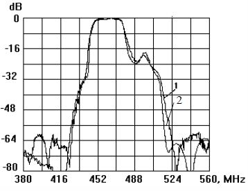
Fig.5 The experimental (1) and the simulated (2) frequency responses ½S21½ for the 460 MHz resonator filter with withdrawal weighted IDTs. Substrate is 49° -YX LiNbO3, Insertion loss is 2.1 dB, fractional bandwidth is 6.0%.
The cuts of LiNbO3 which are known to have high electromechanical coupling coefficient for leaky waves - 41°-YX and 49°-YX, are shown to be promising as substrates for low-loss filters with fractional bandwidth up to 10%. Thick Al electrodes (h/l=0.05) enabled to increase the effective coupling coefficient up to 20-22%. The spurious SAW modes generated in analyzed cuts can be successfully suppressed by means of frequency shift between two cascades of filter. The equivalent circuit model has been modified to account for mechanical reflections and frequency dependent character of attenuation coefficient for leaky waves in thick electrode structure. Charge distribution on the electrodes was taken into account to improve the model accuracy. As a result, very good agreement between simulated and experimental frequency responses has been achieved. Low loss (2-3 dB) longitudinally coupled resonator filters with fractional bandwidth 7% and sidelobe suppression 50-60 dB have been designed and manufactured.
This work was supported in part by TELEFILTER tft GmbH. The authors would like to thank Dr.N.F.Naumenko for helpful advices.