This paper describes a general method for the synthesis of SAW filters based on the composition of basic structure elements and variation of electrode lengths. Optimization algorithm using the scanning window approach allows effective synthesis or improvement of responses for different types of filters. The realizability and adequacy of the synthesis results were improved because the topology constraints and stray elements under simulations were accounted for. The two-dimensional grid method was utilized to develop DMS and RSPUDT filters, including filters on langasite.
Different types of SAW filters have different features and are normally designed by specific synthesis methods. The transversal-type of SAW filters [1] with apodized interdigital transducers (IDT) provide superior group delay variation and roll-off but have high insertion loss. DMS filters [2] can achieve low insertion loss and small size but roll-off is not steep. RSPUDT filters [3] partially combine the advantages of transversal and DMS filters, but their strong discretization disturbs transducer characteristics in wide band designs. Because of the complicated relationship between filter topology and its frequency response, there is no generally synthesis technique that can be used for so many different structures.
Here we propose a general synthesis method that can perform optimization of electrode structures directly. The method is based on the two-dimensional coordinate grid (TDG) representation of transducer structures and the optimization algorithm used in the synthesis routine. The increase of degree of freedom of electrode structures allows the combination of various filter embodiments to improve the responses of SAW filters.
Most of the known topology structures used in various SAW transducer embodiments can be approximately described by the TDG representation as shown in Fig.1-a. Spatial grid periods dX and dY depend on the accuracy of the approximation.

Fig.1 Two-grid representation of IDT (a) and BE (b)
For such a layout representation there are three basic topology elements (BE), shown in Fig.1-b, to form a filter. These elements are strips connected to upper or lower bars of transducers, and free space (or gap). The width of the BE is a unit of the width of electrodes and gaps. The length of a strip is changed with the quantization step equal to the spatial period along the Y-axis. So each electrode can be described by several adjoining strips with the same length, and gaps can be described as the free space elements.
The synthesis routine includes the analysis of arbitrary combinations of the basic elements and the selection of structure, which gives a reasonable optimization criteria. Normally the number of simulation variants is N=3Nx (Ny+1)Nx, where Nx is the number of BE along X-axis within the range for optimization, Ny is the number of layers along the filter aperture.
It is obvious that the optimization of a filter as described above is an unreal task because of the huge number of variants. However, the number can be dramatically reduced for practical application by structure restrictions and design approaches.
The fragment length for structure variations is much shorter than a transducer length. As a rule the fragment does not exceed the wave length. Structure constraints that can be readily applied are as follows:
Most phenomenological models such as COM or P matrix are well suited to periodic or near periodic structures [4]. Because electrode structures synthesized by this TDG method are not fixed, using these models will cause difficulties. Instead, equivalent network model [5] is more suitable for this application. The advantage of this model is its flexibility with variations of finger structures because parameters of cells are determined by edge positions of electrodes.
The basic cell of a transducer is shown in Fig.2. It extends between centers of neighboring fingers and
includes three elements connected in the electrical circuit by transformers r. Every cell can be described by the 3x3 matrix as follows:
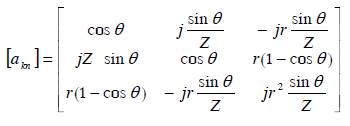
where Z=Zo or Zm are the acoustic impedances for free or metalized surface, respectively; L v i θ =ω / is the angle shift under wave propagation in the cell.
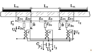
Fig.2 Equivalent circuit model representation
The shunt susceptance B superposing the electrode edges is a complex number. It describes the second order effects such as propagation loss Re(B) and energy storage Im(B). These elements can incorporate asymmetry associated with NSPUDT orientation. The static capacitance per period is modeled by Cp, and
electromechanical coupling is embodied in the ideal transformer with turns ratio r. The turns ratio r depends on charge distribution on the electrodes. Charge distribution is determined by solving the electrostatic problem for the arbitrary electrode configuration.
In order to improve the simulation accuracy, physical parameters for a given material and film properties (thickness, pitch ratio etc.) were obtained experimentally using specially designed test devices.
Acoustic models of transducers are calculated by serial connections of basic cells. The 3-port matrix representation for a filter is then transformed to 2-port and combined with matrices of matching circuits and electrical stray elements in order to generate the filter model as a whole. Matrices of separate transducers can be used for the analysis of these structure elements under the synthesis routine.
The synthesis algorithm is based on step-by-step approaching of current responses and parameters to the
specifications. In the optimization routine, the fragment is applied to different parts of transducers in accordance with a scanning algorithm.
As initial inputs, the designer should determine the substrate material and the model coefficients for such a material, the lengths of transducers and gratings, the distances between these structure units, the fragment length and spatial periods of grids along X and Y directions. Design constraints and optimization criteria should also be set to start with.
The synthesis algorithm developed is based on the published technique used for the synthesis of RSPUDT
filters [7]. Responses of the synthesized filter are simulated for every current structure variants and compared with the specification of the filter. The error Eg between current response and specification is estimated as (1):
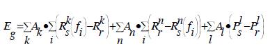
where Rs k(fi) is the value of amplitude response at frequency fi for the k frequency range, Rr k is the required value for the range, Ps l and Pr l is the simulation and required values for l parameter, Ak,l is the weighting coefficients.
The optimization requires Eg to be minimized. This criterion estimates the accuracy of a filter as a whole. In this case, values of filter parameters are calculated as the sum of un-equivalent ones of separate transducers, but parameters of transducers can differ significantly.
The design adequacy can be improved if qualities of transducers are estimated by the optimization routine. In this case the error E, which has to be minimized, is represented as E = Eg + Et1 + Et2, where Et1 and Et2 are errors of transducers simulated in accordance with (1), but for modified requirements and weighting coefficients.
Based on this approach, the optimization software is developed. Depending on the requirement, the synthesis can be realized for tuned or un-tuned filter. Optimal values of matching elements are simulated automatically for current transducer impedances. Parasitic elements are included in the model as well.
As mentioned above, a general optimization and design technique is limited by speed and robustness of the simulations. This method can be applied to practical designs or for the improvement of existing SAW filters. Some practical recommendations and design approaches are outlined as below.
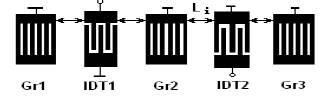
Fig.3 The Generalized topology of a SAW filter
Flexibility and effectiveness of the TDG method can be shown by applying the method to design different types of SAW filters, including filters on substrates that provide natural directivity.
Some results for advanced filter designs on langasite with low insertion loss were published last year [6]. These filters were designed with the optimization approach applied for X-direction only. The grid pitches were 1/8λ. The use of TDG algorithm and shorter grid pitch (1/16λ) allows the improvement of insertion loss and rejection.
The responses of an RSPUDT filter on LGS orientation yxlt/48.5o/26.6o are shown in Fig.4. Film thickness is 0.45 um. The minimal width of fingers and gaps is 1/8λ. 1dB bandwidth is 1.5 MHz (i.e., 1%), out-ofband rejection is higher than 45 dB and insertion loss is about 6.2 dB. Note the response of the unturned filter (dotted plot) corresponds to the typical response of anRSPUDT filter.
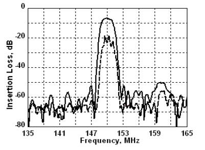
Fig.4 Responses of RSPUDT filter on langasite: solid line – tuned filter; dash line – unturned one
The problem of optimization of low-loss DMS filters is practical because this filter type is widely used for RF applications [7]. TDG was used in order to estimate the adaptability of the method for the synthesis of such filters. The basic structure of 1-2 mode units (Fig.3) was used as an example. In order to improve the response of a typical structure of 4-pole DMS filter, modeling and synthesis algorithm were adapted for the optimization of responses of two units serially connected. The optimization criterion was applied to the total responses of the pair of identical filters. As an illustration of the capability of this synthesis method, the initial and final responses of the 4-pole DMS filters on YXl-36o LiTaO3 are shown in Fig.5. The width of the basic elements used in the synthesis was 1/16λ.

Fig.5 Initial (dotted line) and final responses of DMS
Analysis of the synthesis results shows that variations of both lateral and central gratings effectively influence the frequency response, especially on nearby rejections.
RSPUDT filters are a general filter type that combines the advantages of both transversal and resonant filters. Design results show that the use of TDG method allows the responses of these filters to improve over an ordinary RSPUDT filter.
Responses of RSPUDT quartz filters developed with the optimization of finger and gap widths (along x-axis only), and two-dimensional grid optimization are shown in Fig.6. The width of basic elements was 1/16λ, and the pitch of the grid along Y-axis was 10% of the aperture.
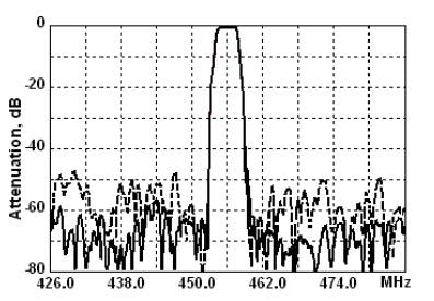
Fig.7 Responses of an RSPUDT filter synthesized by xdirection grid (dotted line) and TDG optimization
The additional degree of freedom allowed the improvement of out-of-band rejection by 10dB on average. The additional apodization not only changes the weightings of current SAW sources but also generate new weightings on reflectors or dummy electrodes. Because of the closely meshed discretization of the transducer weightings, the generation of parasitic modes [8] is reduced as well.
A general synthesis method utilizing the principle of two-dimensional coordinate optimization approach was developed. The method is based on the optimization of electrode structures by varying the basic structure elements. This method’s flexibility allows its applications for the development of different types of SAW filters. In order to simplify filters embodiment, the synthesis routine includes constraints of electrode and gap widths corresponding to technological limitations. The model accounted stray elements and matching circuits for the optimization procedure. Software based on this method was applied for the development of DMS, apodized RSPUDT and the filters on substrates with NSPUDT effect such as langasite. Experimental results agree with the simulations well, and confirm the efficiency of this method for practical SAW filter designs.