The possibility of using interdigital transducers (IDTs) and reflecting lattices with electrode period modulation (dispersion) in resonator filters with longitudinal acoustic coupling on surface acoustic waves is considered. The experimental investigation of test structures with different directivities of the transducer dispersion shows that dispersive IDTs provide for unidirectional excitation. A model developed on the basis of the equivalent-circuit method makes it possible to calculate the characteristics of filters of the class under consideration. It is found that the use of dispersive IDTs and reflecting lattices makes it possible to reduce the insertion losses of devices, to extend their passbands, and to improve their selectivity. A set of filters is designed on the basis of lithium tantalate and lithium niobate acoustic ducts with insertion loss ranging from 1.5 to 3.0 dB and relative passbands ranging from 1 to 8%.
Surface-acoustic-wave (SAW) resonator filters (RFs) with longitudinal acoustic coupling (LAC) are widely used in receiving–transmitting cascades of cellular systems and communications facilities in the frequency range extending to 2.5 GHz. They exhibit low insertion loss, are compact and highly selective, and usually do not require matching elements during connection
in a given circuit. These filters use leaky acoustic waves (LSAWs) and are fabricated on special cuts of lithium tantalate and niobate with a relatively high (5–17%) electromechanical coupling coefficient [1, 2].
Typical structures of sections of LCRFs are presented in Fig. 1. The filter includes two or three transducers located between reflecting lattices.

Fig. 1. Typical structures of resonator filters with longitudinal coupling: (a) asymmetric (first and second modes) and (b) symmetric (first and third modes).
The characteristics are realized by the corresponding spatial arrangement of IDTs and reflecting lattices that ensures the required interaction between resonance modes for various filter designs. Usually, to realize the required characteristics, the filters are made of two or three units connected in series and topologically combined into a single design.
In this study, we consider modified structures and the methods of improving the parameters of LCRFs. These methods involve IDTs and reflecting lattices with a modulated electrode period. The cases of partially modulated transducers and so-called dispersive IDTs realizing linear frequency modulation (LFM) within the IDT length are considered. The use of these structures
makes it possible to reduce the insertion loss in filters and to improve the uniformity of the characteristics in the passband. In particular, the authors of [3] attribute the reduction of the insertion loss to decreased generation of spurious bulk waves.
As a result of the filter synthesis, distances Li between the structure elements ensuring the required filter characteristics may be considerably different from typical gaps between the electrodes in IDTs and lat-tices. If distances Li are too small, problems of fabrication arise. In contrast, if Li are greater than the typical gap width, additional loss occurs owing to the effect of LSAW scattering by topological inhomogeneities [4].
An effective solution of the above-mentioned problems is to adjust the periods of IDT electrodes and of the lattices adjoining the gap under consideration in order to smooth the LSAW transition from one structural element to another. Then, the periods of most of the electrodes in the central parts of IDTs and lattices remain unchanged, thus ensuring the arrangement and interaction of acoustic resonances similar to the arrangement and interaction needed for realization of the required characteristics.
Owing to the change of the character of boundary inhomogeneities in the period-modulation zone, the phase relationships between resonance structures exhibit variations. To develop the filter more adequately, these variations should be taken into account. An additional gap correction is made for reconstructing the original shape of the characteristics. Usually, two or three iterations ensure the convergence of the filter characteristics to the original design parameters for the filter on equidistant IDTs.
Obviously, the results of development depend on the accuracy of the model used for the filter analysis. In this study, we use a modified model of equivalent circuits with the spatial arrangement of elementary sections uniquely related to the position of the electrode boundaries. To make the analysis more reliable, we calculate the charge distribution in irregular electrode lattices by solving the electrostatic problem [5], thus making it possible to improve the accuracy of the calculated filter characteristics.
Figure 2 presents the experimental characteristics of a two-cascade RF with LAC. The structure of the RF is shown in Fig. 1b (first to third modes) in a 50-Ω circuit with no matching elements. The filter is made on the YX1-36 ° cut of lithium tantalate. The relative thickness of the aluminum film is 6.5%. There are 44 and 36 electrodes for the central IDT and side IDTs, respectively. In each of the transducers adjoining the inter-IDT gap, three electrodes were modulated by period.
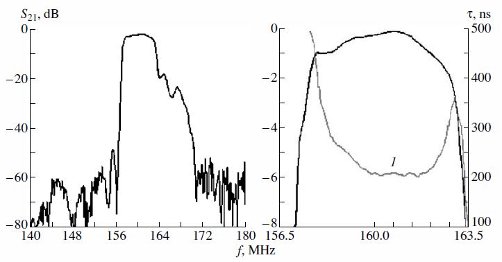
Fig. 2. Experimental characteristics of a two-cascade RF with LAC with the partially modulated electrode period; curve 1 is group delay time τ.
The insertion loss in the filter amounted to about 1.4 dB at the relative passband of 3.5% and a selectivity greater than 50 dB. Note that the insertion loss in the filters of this type is, on average, 0.3 to 0.5 dB less than that in conventional LCRFs that are based on equidistant IDTs.
The above-described designs of LCRFs can be considered a particular case of filters in which the electrode period varies according to a given relationship along the entire IDT length. The transducers of this type are usually employed in dispersive delay lines to realize a frequency-dependent delay and can, by analogy, be called dispersive IDTs (DIDTs). The structures of DIDTs and lattices with modulated periods of reflecting fingers ensure a more flexible approach to formation of resonances and arrangement of resonance peaks within the required passband [6], thus allowing realization of filters with better parameters than those of LCRFs on equidistant elements. In particular, a wider passband, a lower insertion loss, and a deeper rejection in the stop band, i.e., the total improvement of the filter parameters, can be achieved under the various conditions of requirements imposed on the filter.
For determining the basic properties of dispersive IDTs, we have investigated test transducers (Fig. 3) with the linear variation of effective frequency Fi(Fi=v/2di, where di is the spatial period of an electrode pair). The test structures were made on the YX1-36° cut of LiTaO3 with an aperture of 50λ. The transducers were made with linearly modulated spatial electrode periods; the relative frequency deviation
![]()
where Fh and F1 are the highest and the lowest frequencies corresponding to the edge IDT electrodes, respectively, and F0 is the central frequency of the structure. The relative thickness of the aluminum film on the test samples varied from 1 to 6%.
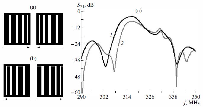
Fig. 3. Test structures with different dispersion directivities: (a) the negative sign of the dispersion, (b) the positive sign of dispersion,and (c) the frequency characteristics of structures (curve 1) (a) and (curve 2) (b).
In Fig. 3c, we present the characteristics of the transducers for different signs of the mutual dispersion (Figs. 3a, 3b); the film thickness is about 5%. It is seen that the difference between the insertion losses in the structures with different combinations of the dispersion signs is about 5.4 dB. The asymmetry of the dispersive transducer radiation is due to the displacement of effective reflection centers toward the low-frequency IDT edge relative to the SAW radiation centers. The phenomenon leads to an increase in the radiation flux toward the high-frequency edge.
The experimental data show that, in dispersive IDTs with unsplit electrodes, an effect of the unidirectional SAW radiation toward the high-frequency IDT section arises. This effect can be used for additional reduction of the insertion losses in LCRFs. It should be noted that the unidirectional character of radiation of dispersive IDTs is most effective in the structure of the first and second modes (Fig. 1a), where the transducers’ directivities are opposite. The filters of this type have dimensions smaller than those of the structures of the first and third modes and are easier to assemble.
For the comparative evaluation of the efficiency of using dispersive IDTs in resonator SAW filters, we have developed identical two-cascade LCRFs with a central frequency of about 315 MHz.
The first filter consisted of a pair of two-mode resonator units connected in series (the first and second modes, see Fig. 1a). Each IDT included 36 electrodes; the frequency deviation was 2.3%. The relative Al-film thickness was about 6%. To achieve the required passband (2%), a central reflecting equidistant grating (screen) was applied; it ensured the necessary magnitude of the acoustic coupling between the input and output resonators.
The structure of the second LCRF was analogous, although it consisted only of equidistant transducers and lattices. The design parameters of both filters were the same. The experimental characteristics of the filters in a 50Ω circuit are presented in Fig. 4.
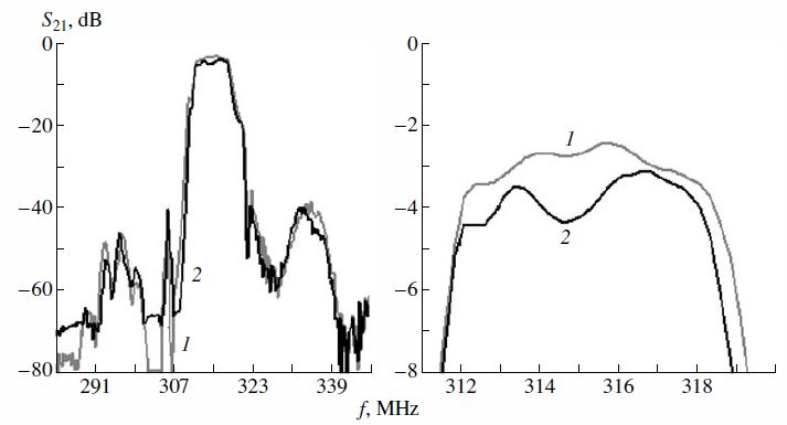
Fig. 4. Amplitude–frequency characteristics of the LCRF with (curve 1) dispersion of the IDT electrode width and (curve 2) equidistant electrodes.
Thus, the results indicate that LCRFs that are based on dispersive transducers exhibit smaller (by about 0.6 dB) losses and have more uniform amplitude–frequency characteristics in the band. Note that the experimental parameters of the filters are in fairly good agreement with the calculated results, thus indicating that the adequacy of the model developed for the calculation of filters of this type. Possible realization of asymmetric filters that ensure effective operation in narrower and wider passbands is illustrated in Fig. 5, where the experimental characteristics of the filters made on YX1- 36° LiTaO3 cut are depicted. The filters have relative passbands of 1.5 and 3.5%. The insertion losses in the filters were 2.2 and 1.9dB, respectively, in the 50Ω circuit. The signal attenuationin the stop bands was greater than 40 dB at 40-and 3-dB-level rectangularity coefficients of about 2.

Fig. 5. Experimental characteristics of the filters with relative bands of (a) 1.5 and (b) 3.5%: (1') in the passband.
The use of the symmetric structure of resonator sections (the first and third modes) usually makes it possible to achieve a wider passband in LCRFs. When the effect of unidirectional wave radiation in DIDTs is employed in the asymmetric structures considered above, the insertion loss is reduced. At the same time, the use of this effect impedes realization of the advantages of dispersive transducers and reflecting lattices in the case of the resonator section shown in Fig. 1b.
For designing symmetric DIDT sections, we proposed and tested the transducer designs with different dispersion parameters of the central IDT. In the transducer design proposed, the dispersion signs are opposite on the left and right sides of the central IDT, while the side transducers are made with the opposite signs of the dispersion response that are correlated with the adjoining region of the central IDT. In this case, in each local region of the resonance structure, the prerequisitesfor the realization of the unidirectivity effect are ensured, thus leading to an additional reduction of the insertion loss in the filter.
In Fig. 6, the experimental characteristics of a twosection filter based on a symmetric DIDT are presented. The filter is made of an acoustic duct on the YX1-41° LiNbO3 cut. Of all available cuts of piezomaterials used in commercial SAW devices, this lithium niobate cut has the maximum coefficient of electromechanical coupling (k2= 17.4%). The deviation of transducer periods was about 7.5%. The filter’s half-power passband was about 60 MHz (or 8%), the rectangularity coefficient was less than 2, the insertion loss was 3.3 dB, and the level of signal suppression in the stop band was greater than 40 dB.
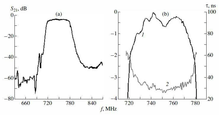
Fig. 6.
Frequency characteristics of a wideband DIDT filter: (a) the total response; (b) (1') in the passband and (2) the group delay time τ.
The obtained results indicate that the use of transducers and lattices with modulated electrode periods makes it possible to improve the characteristics and performance parameters of resonator filters with longitudinal acoustic coupling. The model developed for investigation of nonequidistant resonance structures ensures the adequate analysis of the characteristics of these filters. This conclusion is confirmed by the experimental data. Consideration of the dispersive properties of IDTs and, in particular, the unidirectivity effect makes it possible to optimize the designs of resonance sections and to develop a number of filters on the lithium tantalate and lithium niobate acoustic ducts with insertion losses ranging from 1.5 to 3.0 dB and relative passbands ranging from 1 to 8%. The comparative analysis has shown that filters of this type are characterized by lower insertion losses, better uniformity of the amplitude–frequency response and the delay time in the passband, and higher selectivity as compared with the analogous filters based on equidistant transducers. In addition, for a given substrate material, the range of the realizable passbands is extended.