This work deals with some aspects of resonator performance improvement on unidirectional substrates with arbitrary reflection angle.
A design concept is proposed based on the use of resonators with slight (by about 1-2%, depending on the material properties) frequency increase (or decrease, for opposite phase) of the IDT pitch in the transducer center for bi-directional substrates. For naturally unidirectional orientations properly placed linear chirp transducers with pitch variation of the same order of magnitude are found to give practically useful results, while for arbitrary phase angles in between of these two extreme cases the position of the transducer pitch maximum (minimum for opposite phase) is shifted from the center to the corresponding side of the transducer in accordance with the phase.
Relevant the results are compared with experimental data on langasite substrates.
NSPUDT, SAW, resonator, transducer, phase
SAW resonators [1, 2] are commonly used in filters and sensors. In the latter the choice of substrate for particular sensor application may result in arbitrarily oriented cuts that as a rule do not present the convenience of zero (or 90, 180 and 270) degrees phase of the reflection coefficient as on “bidirectional” and on “pure unidirectional” substrates.
As shown by Uno [3] and later by Ebata [4] resonator properties on ordinary substrates with bi-directional transducers may be substantially improved by using different pitches in transducer region and in grating regions. Additionally in QARP resonators [2] the pitches are slightly modified in order to obtain negligible disturbance of electrode periodicity and thus to reduce the level of conversion into bulk waves at discontinuities related to the IDT-grating transition region. In this work the QARP concept is extended to application of transducers with varying pitch and new design concepts are found that are generalized to arbitrary phase angle of the reflection coefficient. For the full 360 range of existing phase angles the space variations of the IDT pitch are found that simultaneously improve the resonator conductance, reduce the level of unwanted side band signals and eliminate the abrupt change of periodicity characteristic of ordinary designs [5] thus realizing the conditions similar to those existing in QARP [4].
As was shown by Uno [3] in order to obtain highest resonator conductance and lowest level of spurious out-of band signals the maximum of IDT conductance should coincide with the resonator resonance frequency or to be relatively close to it.
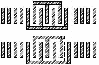
Figure 1. Illustration of the design concept.
This is achieved by changing the IDT central frequency (increasing it in most cases, while examples of materials exist where it needs to be decreased). Slight detuning from discussed by Uno optimal conditions used in QARP approach [4] does not affect much the resonator performance, while giving the flexibility of changing the IDT pitch in such a way, so as to avoid narrow or wide gaps between reflectors and the transducer.
In case of a substrate where a NSPUDT conditions are met, such as for example langasite (yxlt/48.5º/26.6º, Euler angles λ, θ, μ = 0, 138.5, 26.6º) the shape of conductance has two equal maximums with values that are almost two times lower than the single one of a bi-directional IDT. This is the reason why resonators with such transducers have somewhat lower conductance at resonance and higher relative level of out-ofband unwanted signals. Applying the Uno concept and simply shifting the IDT frequency up or down increases the relative level of unwanted signals.
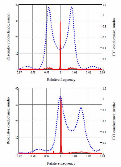
Figure 2. Example of resonator (solid) and IDT conductance for ordinary IDT (top graph) and for linear chirp IDT (lower graph) on a NSPUDT substrate.
In order to overcome this drawback the unidirectional transducer may be in one or another way transformed to acquire some features of a bi-directional IDT. Some past experience has shown that transducers with pitch variation notably chirp transducers at some conditions may acquire
pronounced unidirectional properties on ordinary substrates [6].
When a NSPUDT transducer has a linear chirp structure it loses to some extent its unidirectional properties and its conductance shape becomes more similar to that of a bidirectional IDT. Decreasing or increasing the pitch causes the left or right peak of the IDT conductance to be enhanced, respectively, while the other one is suppressed This design concept is illustrated in Fig. 1 where the upper layout corresponds to a known approach (for example [5]) where an additional gap between the IDT and the right reflector is used and the lower layout shows how the IDT pitch is changed in order to modify the IDT conductance and to eliminate the additional gap between the IDT and the reflector, thus realizing to some extent the principles of QARP resonators [4].
Figure 2 illustrates the behavior of the IDT conductance and of the resulting resonator response for both designs (shown in Fig.1) where the relative frequency is the frequency normalized to the Bragg frequency of reflectors. Both structures are modeled for the reflection phase strictly equal to 90º most favorable for NSPUDT effect. Note that the reflection phase may have different definitions due to arbitrary choice of the reflection origin point. Unlike in [5] we will use here the
following phase definition [7] ψ = Arg(k12ζ* ⁄ ζ) = Arg(k12) –2Arg(ζ). It means that the case of ψ = 0 corresponds to ordinary substrate with thin electrodes, ψ = 180º corresponds to the opposite bi-directional case and ψ = ±90º corresponds to maximal NSPUDT effect, positive ψ corresponds to larger radiation from right side of IDT. The reflectors contain 263 strips and the transducers have 126 electrodes. The periods of the gratings are the same in both cases and correspond to the required central frequency that preferably would be in the middle of the Bragg band. The pitch of the chirp transducer changes from that of the gratings to a value slightly lower (in this example by about 0.9%) or slightly larger (in general case). As a result the larger maximum of the chirp IDT conductance shifts closer to the Bragg frequency of reflectors. The position of reflectors is thus slightly adjusted together with the change of the IDT dimensions in order to realize QARP-like conditions [4].
Comparison of the responses in Fig.2 demonstrates about 10-15% increase in resonator conductance and some decrease of the relative level of unwanted signals. Improvement in properties is further enhanced by reduction of scattering from the abrupt change in periodicity.
This design approach becomes seriously more important for practical cases of non-ideal natural unidirectivity. As a rule the phase of the reflection coefficient depends on the thickness of the metal. For langasite the useful value of reflection from the gratings is achieved at a thickness of Al above 1% of the wavelength. At this thickness the phase ψ reaches 120º for 50% metallization ratio and may be even larger with wider electrodes.
As shown in Figure 3 the ideal NSPUDT case with ψ = 90º is rarely achievable in practically interesting cases. In order to obtain sufficiently high reflection amplitude one has to choose high enough aluminum thickness (2-4% of the wavelength) and metallization coefficient (between 50 and 75%). In these conditions the reflection phase stabilizes closer to 120º and this feature has to be taken care of in the design, for example as in [5].
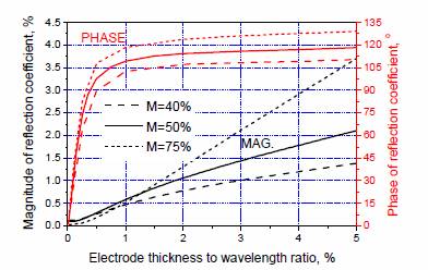
Figure 3. Amplitude and phase of the reflection coefficient of Al strips with
different metallization ratios on langasite yxlt/48.5°/26.6°.
If the variable electrodes pitch concept described above is applied to a substrate with ψ = 0, the symmetry has to be observed in order to obtain a QARP-like response. For this case the pitch in one half of the IDT goes down linearly and then it goes up in the second half. The highest instantaneous frequency of the IDT is reached in the middle of the structure, while the average frequency satisfies QARP conditions. For the ψ = 180º the inverse relation is true and the IDT frequency is the lowest in the centre of the structure. The modeling has shown that the resonator performance in these arrangements is very close to the performance of the corresponding QARP arrangements. But in such cases the variable pitch is usually unnecessary.
However, in this way we get a useful hint for approaching intermediate cases when the reflection coefficient phase is not 0, 180, 90 or 270º. The intermediate phase difference requires intermediate positioning of the lowest (or highest) pitch region inside the transducer area.

Figure 4. Electrode pitch versus electrode number for 120° reflection phase.
This is illustrated in Figure 4, where the details of resonator design are shown for ψ = 120°. The linear change of IDT pitch is approximated by 9 sections with 14 electrodes (126 electrodes total) with constant pitch in each section. The pitch of the 263 electrodes identical gratings is equal to 8.077 microns and the pitch of the IDT section grows from 8.09 microns in the first section from the left to 8.172 microns in the seventh section from the left and falls to 8.144 microns in the ninth (last) section. Note that for such small pitch variations linear change of the pitch used in this design practically does not differ from the linear change of the IDT central frequency as in chirp structures, and both variants may be used with similar results.
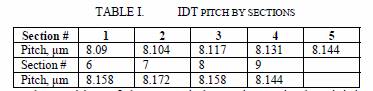
The position of the IDT pitch maximum in the vicinity of the seventh section is realizing to some extent the condition of maximum energy transfer discussed in [5]. This position is relatively insensitive to slight shifts and the resonator performance is not much affected by modifying the linear chirp pitch variation by partitioning into sections as in Table 1. A reasonable suggestion for the placement of the IDT point where the pitch differs the most from the gratings pitch is the
following:

where XM is the coordinate of this point measured from the IDT centre (positive to the right), L is the IDT length, and the phase ψ varies from -180º to 180º. The IDT pitch must be smaller than gratings pitch if |ψ| < 90º and larger if |ψ| > 90º. Both variants are applicable if ψ is quite close to ±90º
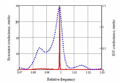
Figure 5. Resonator performance as designed for langasite
Modelling of a resonator designed for LGS, following the Table 1 with propagation loss data fitted from experiment, demonstrates a low level of out-of-band signals, high conductance (Figure 5), and large separation of the resonance and antiresonance frequencies.
Figures 6 and 7 show the comparison of the experimental and modelled responses for the design described above (with COM-parameters corrected from experimental data). Test samples with metallization ratio about 70% were initially obtained with an excessive thickness (about 0.6 microns). This has resulted in increased reflection amplitude in the IDT and in gratings and correspondingly increased the Bragg bandwidth that can be evaluated quite precisely from the distance between the right and the left additional peaks in Figure 7. Etching excessive metal in 0.8% KOH solution for about 6 minutes has resulted in a correct value of the Al film average thickness (about 0.4 microns) that was initially used for this design in order to obtain low level of out-of-band signals.
The agreement of the model and of experimental data is quite satisfactory, especially in details related to the out-ofband features shown in Figure 7.
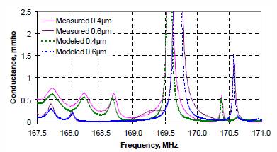
Figure 7. Measured and modelled conductance of the resonators at small
scale showing the out-of-band response details.
It is important to note that the photomask for the test samples has been obtained with the simplest averaging procedure while using relatively large step of the electrode width. The error accumulating from such coarse implementation did not affect the response shape significantly.
The design method was presented for single port resonators on substrates with arbitrary phase of reflection coefficient, thus eliminating abrupt changes in periodicity as in QARP. As a result, for any phase difference, this method enables devices to have a low level of out-of-band response, large conductance and large difference between the resonance and the antiresonance frequencies. This design is expected to be useful for waves that are especially sensitive to perturbations in the periodicity, such as leaky waves. The design concept was verified and good resonator performance has been achieved with Al electrodes on langasite.