Transversal filters with very high shape factor have been developed based on multiharmonic and withdrawal weighted transducers with isolated sections. The developed simulation technique provides excellent results both for in-line filter structures and those with multistrip couplers. The experimental results are presented for IF filters manufactured on YZ-LiNbO3 and ST-quartz substrates. In-line filters exhibit SF in the range 1.15-1.2 and for MSC filters, SF values 1.05-1.1 have been obtained. For all filters the stopband rejection is more than 50 dB.
Increasing demands for transmission-capacity of modern radio-communication and TV systems in the available radio frequency bands require devices with more perfect selection. In recent years SAW filters have been intensively developed to improve simulation accuracy and increase selectivity in the intermediate frequency (IF) range [1].
When insertion loss is not an essential parameter, filters based on apodized bi-directional interdigital transducers (IDTs) allow to realize sufficiently high shape factor (SF), low passband ripples and high out-of-band rejection. Special requirements for amplitude and group delay responses can be also provided [2]. Such SAW filters are usually implemented as multistrip coupled (MSC) filters consisting of two apodized IDTs located in different acoustic tracks and coupled by means of multistrip coupler and require substrates with high electromechanical coupling coefficient, such as LiNbO3. The structure of in-line filter can include, for example,apodized and withdrawal weighted (WW) transducer. Though some attempts have been made to use twoapodized IDTs in a common acoustic track, they were not successful [3].
A development of synthesis methods and accurate models taking into account second-order effects and an application of new layout structures allow to realize SAW filters with SF about 1.1. This value is usually considered as the practical limit for transversal SAW filters. In the present paper the transversal SAW filters with improved SF (about 1.05-1.1) have been developed based on multi-harmonic (MH) transducer. In our opinion, such structures provide the advanced possibilities for both in-line and MSC filters.
The improvement of SF and rejection level has been also demonstrated for in-line filters with so-called withdrawal weighted transducer with isolated sections (WW-IS). It is shown that such IDT provides more accurate approximation of specified frequency responses.
The simulation technique is based on the method of frequency taps which can be applied for digital filters [4]. This method allows to synthesize amplitude and phase responses independently from each other. A synthesis procedure includes correction of amplitude and phase (or group delay time) frequency taps within a specified frequency range and simulation of a transition function corresponding to these new taps. Dependent on filter type, the procedure may be applied to one IDT or both transducers simultaneously.
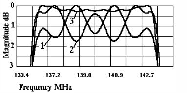
Fig.1. Simulated passband amplitude responses of WW transducer (plot 1), apodized IDT (plot 2) and in-line filter (plot 3).
For example, if WW transducer corresponding to quasi-rectangular response is used as IDT of an in-line filter, an apodized IDT can be synthesized so that to compensate the ripples of fixed WW transducer (Fig.1). It can be seen that due to the apodized IDT the amplitude ripples of WW transducer (about 1.7 dB) are reduced to 0.1 dB in the final filter response. For MSC filters, both apodized IDTs can be designed for optimal selection and minimum ripples.
Though the method of frequency taps is inferior to some known optimization algorithms [5,6], from ourpoint of view it is more flexible and convenient as a designer’s tool. The method provides the possibility of local correction and predistortion of filter response onaccount of experimental data for circuit effects, diffraction loss etc. including amplitude and phase corrections of SPUDT filters. It should be noted that the results of optimization procedures (such as Remez exchange algorithm) can be used as the initial approximation for further filter design. It is also helpful for filters with complicated frequency response and when special requirements are specified for group delay time response.
A proper modeling for both in-line and MSC filters is based on modified cross-field Mason-Smith equivalent circuit model [7]. The required high accuracy of simulated transfer function can be achieved only if the second-order effects are taken into account by means of suitable correction of IDTs. The following second order effects have been accounted in filter design: finger reflections; charge distribution on IDT electrodes; energy storage effects; propagation loss due to scattering into bulk waves; finger resistance; circuit effects; feedthrough signal.
One of the main reasons which leads to degradation of filter selectivity is circuit effects or regeneration effects caused by interaction between SAW and a load. The simulated conductivity plot of the conventional apodized IDT with quasi-rectangular frequency response is shown in Fig.2 (plot 1). For this case, the weighting function is given by w(t)=wT(t)sin(pt/To)/(pt/To), where wT(t) is Tailor’sfunction and -22To £ t £ 22To.
The amplitude ripples near the passband edges more than twice exceed an average conductivity level in passband. These ripples cause distortions of filter response in the transition band. To decrease the amplitude ripples, a “slanted” overlap apodized IDT has been used. However, the ripples remain high when the number of sidelobes in a filter impulse response is more than 30-40.
To realize the synthesized impulse response, we have used so-called multiharmonic transducer (MH) [8], which structure is shown in Fig.3. The MH transducer comprises several electrode areas with different electrode periods in each area. In Fig.3, these areas are marked as 1,3,5. The central area (1) is carried out as a conventional overlap IDT generating the first SAW harmonic. The distances between sources in the other IDT area correspond to odd harmonics of the transducer. In Fig.3, the areas marked as “3” and “5” refer to the third and the fifth harmonics, respectively. Since the total efficiencies of SAW sources in harmonic areas are weaker than in the section (1), the weights in these areas have been increased
an(i) = a(i) n kn,
where a(i) is an old weight value, n is a harmonic number, kn is a coefficient accounting for generation efficiency of the n-th harmonic.
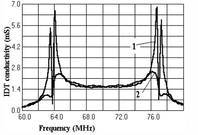
Fig.2. Simulated conductivity response of the conventional apodized transducer (plot 1) and multiharmonic transducer (plot 2).
It should be mentioned that the division of IDT structure into the areas with different source periods causes spurious responses at the frequencies f0 /n (where f0 is a center frequency of a passband). To reduce these responses to desired level, different harmonic structures can be used in the input and the output IDTs. The area lengths and the harmonic numbers in MH transducer depend on the specified passband and SF values of a designed filter.
In our opinion, the MH transducer has several advantages over uniform IDTs. First, the reduction of anumber of sources decreases SAW regeneration effects in IDT. In Fig.2 (plot 2), the conductivity of MH transducer is plotted. It can be seen that the conductivity ripples are excluded.
Second, the diffraction loss in each n -harmonic area is also decreased because the weights are increased (approximately by n times). This effect allows to reduce the influence of charge distortion effect at the electrode tops and to provide more accurate realization of weighting function. It should be emphasized that in terms of efficiency MH transducer is similar to IDT either with split or with single electrodes. It depends on the electrode structure of central area of MH transducer.
Two examples of IF MSC filters are shown in Fig.4 and Fig.5. Both filters are fabricated on YZ-LiNbO3 substrates.
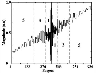
Fig.3. Overlap structure of multi-harmonic transducer
The first filter has 18% bandwidth(Fig.4) and consists of two overlap MH transducers, each 940 fingers, coupled by MSC. The third and the fifth harmonic structures have been used for transducer design. The aperture is 62l . In order to reduce the edge effects, the simulated weights have been corrected and the circuit effects taken into account. The passband ripples are about 0.5 dB peak-to-peak, while the stopband rejection is better than 50 dB. The shape factor (at levels 40 and 3 dB) is 1.06. The filter with such parameters requires more than 80 sidelobes.
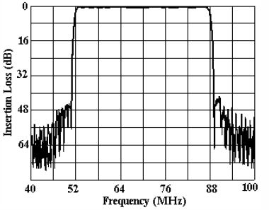
Fig.4. S21 frequency response of 18% bandwidth MSC filter based on MH transducer: IL=22dB, SF = 1.06.
The second filter has 50% bandwidth (Fig.5). Itsstructure is identical to that of the first one, but IDTs include only the third harmonic areas. Each MH transducer consists of 236 fingers. The aperture is 75l . The second-order effects have been also compensated. The passband ripples are less than 0.9 dB peak-to-peak and stopband rejection is better than 40 dB.
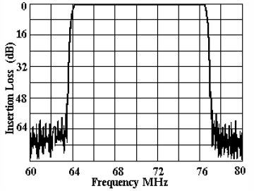
Fig.5. S21 frequency response of 50% bandwidth MSCfilter based on MH transducer: IL=29.5dB, SF(40/3dB) =1.07.
The improved selectivity can be obtained in filter with WW-IS transducers due to better distribution of selectivity between two transducers. WW-IS transducer structure is shown in Fig.6-b,c. The isolated sections are located between the electrodes of opposite polarity.
As initial approximation, the charges on electrodes located near the gaps between the sections (or between active electrode and section) have been taken as gs=g0(ns+1), where g0 is an average charge on active electrodes of WW IDT, ns is the number of serial located section. For example, WW-IS structures shown in Fig.6 correspond to gs=g0/2 (Fig.7-b) and gs=g0/3 (Fig.6-c).
The accurate charge distribution is obtainable if the element factor is taken into account[9].
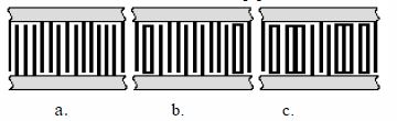
Fig.6. Withdrawal weighted IDT structures: a - WW structure; b,c - WW structures with isolated sections.
The smaller available weights are used in theWW transducer synthesis, the better approximation of desired impulse response can be provided. The synthesisprocedure of WW-IS transducer is identical to the common one. However, some additional restrictions have to be imposed. The main one is the condition of layout realization. In order to place ISs in the single acoustic track, the definite combinations of weights and signs are allowed.
The comparison of simulation results for initial and WW-IS transducers shows a good agreement between their responses (Fig.7) at passband and transition bands. The use of WW-IS transducers allows to improve SF and rejection level of in-line filter. The passband ripples of WW-IS transducer can be compensated by means of MH transducer as shown in Fig.1.
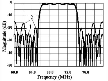
Fig.7. Simulated S21 responses of overlap IDT (plot 1) and WW-IS transducer (plot 2).
Fig.8 shows the measured frequency responses of the in-line filter fabricated on ST-quartz substrate. Filtercomprises MH overlap IDT combining the third and the fifth harmonics and WW-IS transducer. The aperture is 55l . The obtained passband ripples are about 0.35 dBpeak-to-peak, deviation from linear phase is about 3 deg. peak-to-peak, stopband rejection is better than 50 dB, and shape factor (at levels 40 and 3 dB) is 1.18.
Transducer structures have been presented whichallow to improve shape factor and stopband attenuation for transversal SAW filter. The multiharmonic IDT structure is suitable for both MSC and in-line filters. The WW transducer with isolated electrode section is preferable for in-line filter.
The IF MSC filters based on MH transducerswith relative bandwidths 10-50% have been designed and fabricated on YZ-LiNbO3 substrates. Measured shape factors are 1.06-1.12 while stopband rejection is 45-55 dB and passband ripples less than 0.5-1.0 dB. In-line filters have been designed and fabricated both on YZLiNbO3 and ST-quartz substrates. For bandwidth range 2-15%, the experimental characteristics exhibit shape factors 1.09-1.2 and stopband rejection 40-45 dB.
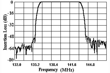
Fig.8. Measured response of the in-line filter on STquartz substrate: IL=21dB, BW(3dB)=7.35MHz, SF(40/3dB) =1.18.