RSPUDT filters based on different width split fingers for IF applications have been developed. Such filters provide improvement of insertion loss comparing to DART-RSPUDT filters. A new optimization procedure for RSPUDT filter design has been proposed, based on the adjustment of RSPUDT through a synthesis grid of narrow structure elements. The width of these elements is equal to or smaller than a minimal finger width of a basic SPUDT structure. This approach provides additional improvement of filter characteristics. DWSF-RSPUDT filters on quartz and 112o-LiTaO3 are reported. Relative bandwidths of these filters are 1–3% and out-of-band rejection about 40 dB. Insertion loss is 1-3 dB better than that for equivalent filters based on other RSPUDT structures.
Currently SAW filters based on resonant single-phase unidirectional transducers (RSPUDT) are widely used as IF channel selection filters in many wireless systems. The design of such filters is aimed to achieve smaller size, lower insertion loss and better other frequency responses. Usually RSPUDT filters are based on DART (distributed acoustic reflection transducer) [1] or EWC (electricalwidth controlled) [2] transducers. The creation of resonant cavities inside SPUDT leads to better frequency characteristics due to a longer impulse response. It corresponds to alternative areas of positive and negative values of reflection weighting, i.e., areas with local directivity in the forward and backward directions.
Improvement of insertion loss of RSPUDT filters can be achieved by more effective SPUDT structures, such as different-width split fingers (DWSF) and Hanma- Hunsinger structure (H-H) [3,4]. The insertion loss of the SPUDT depends on electrical 1/Q factor [5] and its directivity. The electrical 1/Q factor for DWSF is close to bi-directional split-finger transducer and is about 1.65
times of that for DART [6]. Because of narrower fingers, operating frequencies for filters based on such structures are lower than that for DART SPUDT of the same line-width. But there are many IF applications where DWSF filters are competitive with other SPUDT filters, when small line-width is not an issue for current photolithography technology.
In this paper a practical concept of RSPUDT filter design is proposed. The adjustment of finger positions and widths provides a more flexible synthesis procedure. The novel design conception allows to improve filter characteristics comparing to RSPUDT filters based on fixed finger width configurations. As a result, the insertion loss of DWSF-RSPUDT filters achieved is 1-2 dB better
than that of the equivalent DART-RSPUDT filters [7]. Performances of such filters on quartz and lithium tantalite substrates are presented.
The transformation of split-finger transducer to H-H structure is shown in Fig.1. Left and right sides of the SPUDT structure have opposite directivities in order to attain resonant cavity. The width of a narrow finger is 1/16λ and the width of a wide finger is 3/16λ. The transformation can be carried out by two approaches:
The first approach (Fig.1-a) is to shift neighboring finger edges of the split-finger pair by 1/16λ. The shift direction depends on the directivity. In this case, all gaps are equal to 1/8λ, including a gap between the sections of opposite directivities.
The second approach (Fig.1-c) is to fix the finger centers of a split-finger pair and change their widths to obtain a required directivity. The gap width between sections of opposite directivities can be 1/16λ. In this case the distance between two adjacent reflection centers is 1/4λ. This is an optimal distance for local resonant cavities. Because the synthesis of RSPUDT filter needs to include such resonant cavity inside transducers, this structure is more preferable for RSPUDT filter design.
Normally a synthesis procedure of RSPUDT operates with topological elements that differ by transduction and reflection weights within one wavelength. Allowed combinations of these weights depend on SPUDT structure. For DWSF RSPUDT, transduction and reflection weights are not correlated, i.e., they can be independent with each other within one-wavelength section.
One-wavelength cell without reflection corresponds to ordinary split-finger structure (Fig.1-b).
By varying combinations of cells with different combinations transduction and reflection weights, a required RSPUDT can be synthesized with an optimization procedure.
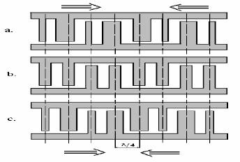
Fig.1 Transformation of split-finger structure (b)
to regular DWSF structures (a and c)
Smith’s equivalent circuit model is used for RSPUDT analysis and synthesis. The model is based on a representation of topological elements (finger or gap) by a 6-pole electro-acoustical equivalent circuit. This allows modeling of arbitrary structures of transducer cells in a synthesis routine. An equivalent circuit can include the modeling of a variety of second order effects such as reflection, resistance, propagation loss and storage energy effect.
The accuracy of simulation depends on the accurate description of these parameters and their dependency on relative metal thickness and frequency. The model we used included the measurement results of test structures and simulations adjusted to experimental results. The synthesis routine includes the following steps: local variation of a section of the transducer structure, and the simulation of the frequency response and the comparison with the filter requirement. As a criterion the general error is estimated. The error is simulated as:
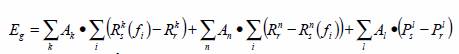 where Rs^k(fi) is the value of simulated amplitude response at frequency fi for the k frequency range, Rr k is the required attenuation value for this range, Ps l is the simulated value of a certain parameter, Pr l is the required value of that parameter, Ak,l is an error weight for a specific frequency range or a parameter.
The first part corresponds to out-of-band attenuation of amplitude response, the second part is for passband amplitude response and the third part is for other parameters such as insertion loss, phase or group delay deviation, etc. Examples of the simulation of errors for outof- band and passband amplitude responses are shown in Fig.2. Errors for both cases are shown as the grey areas. Only the response points that are above the required levels for rejection band and the response points that are below the required levels for passband amplitude are included in the general error.
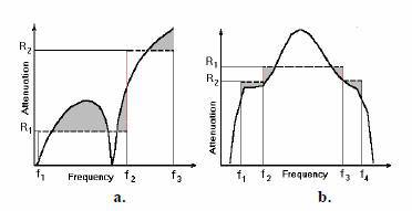
Fig.2 Error simulation for rejection (a) and passband (b)
Variations of a transducer structure are done within a section. It includes all allowed topological variants of DWSF cells. For every variant, frequency response for the matched filter is simulated and the error Eg is estimated. The error is compared with an error Ego, which corresponds to a base transducer structure. If the current structure variant provides a error Eg smaller than Ego thecurrent structure becomes a new base structure. Then the following section is optimized using the same algorithm. By varying weights Ak,l, a designer is able to operate the synthesis routine and finalize the design. A successful choice of the initial section can affect the speed and the final result of the synthesis.
It should be noted that the second transducer is fixed under the optimization. When the synthesis of the first transducer is done the algorithm is applied to the second transducer or grating. The procedure can be repeated several times until the minimum error is reached.
Local minimum value and design quality of RSPUDT filter depend on the accurate choice and description of optimization parameters and their weights and initial approximation of the filter, e.g., length of transducer and grating, metal thickness etc., which can be estimated from other simple synthesis programs or by the designer’s experience.
The estimation of simulated responses is then done for the matched filter. Because the transducer structure is changed with each iteration, matching circuits providing an optimal match should be changed accordingly. The algorithm determining these matching circuits includes the estimation of the average impedance of transducer within the filter passband and the simulation of values of matching components. These matching circuits provide complex-conjugate impedance for the current transducer structure and account for source and load impedances and certain parasitic elements.
The optimization routine is applied to the synthesis of RSPUDT filters based on fixed DWSF structures as in the first step of the synthesis procedure.
The capability of a typical synthesis algorithm is limited because a fixed SPUDT structure is not flexible enough. In order to reduce the general error and to improve the design result a new synthesis approach was proposed. This approach is based on representing a transducer cell as a grid including topological elements having fixed width. These base elements can be either gaps or fingers. Polarities of the fingers can be arbitrary.
Such grids with corresponding element width of base elements can describe every SPUDT structure. The maximum grid width for a SPUDT is equaled to the minimal common multiple for the width of topological elements of the structure. For instance, the maximum grid width for DART-SPUDT is 1/8 of wavelength and a reflector can be represented as 3 identical base element positioned side by side. The maximum grid width for Hanma-Hunsinger structure is 1/16 of wavelength. A transducer structure, synthesized for a fixed DWSF, is transformed into the grid description and used as the initial structure for further optimization. Such a two step approach allows minimizing simulation time needed for DWSF-RSPUDT structure synthesis. In order to control a topology of a synthesized RSPUDT, a designer is able to set some limitations, e.g., maxima of finger and gap width can be limited.
As simulation shown, the adjustment approach can significantly reduce the error Eg achieved by a fixed DWSF structure under RSPUDT filter synthesis.
Final DWSF structures comprise electrodes with irregular placement and width of fingers and gaps. In order to simulate filter response more accurately, the task of charge distribution should be solved for these electrode structures and included in the synthesis algorithm.
As an example, simulated response for RSPUDT with fixed DWSF structure and response synthesized by the additional adjustment procedure are shown in Fig.3.
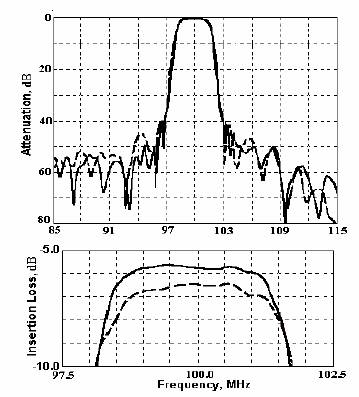
Fig.3 Simulated responses for fixed DWSR (dashed line)
and adjusted DWSF structures (solid)
Minimal general errors Eg were achieved for both RSPUDT filters. The simulation example shows that the application of the adjustment procedure allows to achieve better results for both out-of-band rejection and insertion loss.
IF RSPUDT filters based on DWSF were designed both on quartz and 112o-LiTaO3 substrates. The experimental response of a 71 MHz filter is shown in Fig.4, with a bandwidth of about 1.1 MHz. The filter is based on H-H RSPUDT structure, packaged in 13.3 x 6.5 mm SMD package, and has a insertion loss of 10.3 dB and out-of-band rejection of more than 40 dB. An identical filter was designed as DART-RSPUDT. Insertion loss of the DART-RSPUDT is about 13.8 dB, i.e., about 3.5 dB higher than that of the equivalent H-H RSPUDT filter.
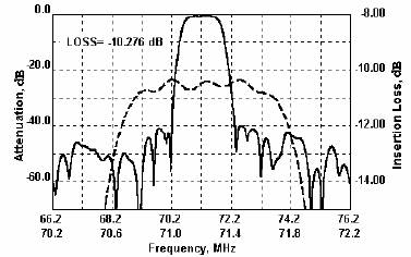
Fig.4. Response of a 71MHz H-H RSPUDT filter on quartz
Most of narrow band RSPUDT filters are designed on quartz substrates. Because of the large value of the storage energy effect, central frequencies of quartz filters are very sensitive to metal thickness variations, especially when the relative thickness is more than 1.5-2.0%. Filters on 112o- LiTaO3 substrate provide wider fractional bandwidth or better insertion loss for the same relative bandwidth than filters on quartz substrate. Besides, as the energy storage effect is about half of quartz, manufacturing variation of such filters is better than quartz filters.
Experimental response of an RSPUDT filter on 112o- LiTaO3 substrate is shown in Fig.5. The relative 3dB bandwidth is 3.3% and insertion loss is about 5.5dB. 7mmx5 mm SMD package is used for this filter.
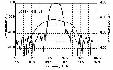
Fig.5 Response of a H-H RSPUDT filter on 112o-LiTaO3
The experimental result of a narrower band filter on 112 deg lithium tantalite is shown in Fig.6.
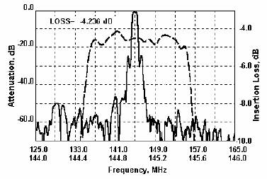
Fig.6 Experimental response of DWSF RSPUDT filter
on 112o LiTaO3
The fractional bandwidth of the 145 MHz filter is about 0.7%. The adjustment procedure of DWSF was applied for the filter design. The insertion loss achieved is about 4.0 dB. 9.1mmx4.8mm SMD package is used for the filter. The out of band rejection is more than 50 dB.
Simulation and experimental results have shown that RSPUDT IF filters based on periodical DWSF sequences can achieve better insertion loss than DART-RSPUDT filters. Depending on relative bandwidth and shape factor the insertion loss improvement can be 1-3 dB.
A new approach of RSPUDT filter synthesis is presented. It includes a synthesis routine based on a grid of topological elements narrower than the SPUDT structure elements. This allows to improve design results comparing to the periodical SPUDT structures.
Examples of DWSF-RSPUDT filters on 112o-LiTaO3 provide wider bandwidth or better insertion loss than that on quartz substrates. These filters can be competitive for many IF applications