New structures of slanted transducers are described. These structures are based on a variation of weighting along a filter aperture. The first quasirectangular structure has equal lengths but different numbers of fingers for every frequency channels. The second partially-weighted transducer comprises with different weighting for lateral and central frequency channels. The use of such structure allows to improve some filter parameters, such as insertion loss and metal pattern dimensions.
An implementation of the slanted or tapered transducers allows to reduce insertion losses and to
improve triple-transit signal suppression for wider frequency bands in comparison with ordinary transversal filters. SAW filters based on slanted transducers have a widespread application as key components in modern wide-band mobile communication systems. Because of this, such filters have been under extensive development in recent years [1-4].
Slanted transducers (ST) can be represented as a number of parallel acoustic channels or comparatively narrow-band sub-filters connected electrically in parallel. The relationship between amplitudes and phases of SAW excited in each acoustic channel can be brought closer to the optimal one for the substrate material. It provides additional opportunities for a synthesis of wider singlephase unidirectional transducers (SPUDT).
Tap weights of a single sub-filter response determine a transition an out-of-band rejection. The most ST used now have the same finger structures in every sub-filter. Because lengths of high frequency and low frequency channels are different, amplitude responses of slanted filters are unsymmetrical, i.e. a high frequency transition band is wider than a low frequency one.
Besides an influence of layer upon a filter responses differs in dependence on the layer position. Lateral layers that have central frequencies closed to edge frequencies of a pass band predominantly determine transition bandwidth of a filter and out-of-band rejection. As for
central layers they determine a filter efficiency or insertion loss.
In this paper novel slanted transducer types based on different weighting of layer structures are considered. A use of such transducer allows to improve some filter parameters.
A basic structure of quasi-rectangle slanted transducer (QRST) is shown in Fig.1. Because layer lengths (Ln) of the transducer are identical (Ln » Lo) high and low frequency transition bands are identical too. It is clear the a layer frequency is higher the number of wavelengths for this layer is bigger. In order to provide electrical connection of extra fingers to busbars vertical strips are
included into the structure.
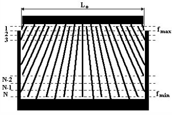
Fig.1 Structure of quasi-rectangle slanted filter
Transducers can be performed as quasi-slanted ones [5]. In this case a set of parallel acoustic channels have a uniform electrode widths, periodicity, and aperture An in the direction of SAW propagation for an each channel. The like straight electrodes in the adjacent channels are
electrically connected in equipotential stepped electrodes using connection layers with the apertures dAn. A simulation yields that if the ratio dAn /An is about 15¸20, then the effect of connection layers on the frequency responses of the filter can be disregarded. These intermediate layers can be used for a connection with additional busbars by horizontal strips as shown on Fig.2.

Fig.2 Layout fragment for intermediate channels
A transfer function of the n-channel may be derived as
Hn(f) = HIn(f) x HOn*(f),
where HIn(f) and HOn*(f) are transfer function and complex conjugate one of input and output transducers correspondingly.
In contrast to ordinary slanted filter transfer functions of sub-filters differ each from other because of different finger number for each channel. Therefore, an overall amplitude response of quasi-rectangle slanted filter (QRST) may be expressed by:
Because sub-filter lengths are identical, high and low frequency transition bandwidths are identical too. They are close to a high frequency transition band for an ordinary slanted filter with the same weighting functions. So a frequency response of such filter becomes more symmetrical. Because specifications for the most of filters require symmetrical responses a use of QRST allows to reduce a filter lengths. Besides diffraction distortions are smaller because of more homogeneous metalization along propagation directions for SAW with different frequencies.
A design of quasi-rectangular slanted filters is based on the synthesis of high frequency transition band requirements. Both transducers are synthesized so that to provide required transition bandwidth and rejection level, i.e. a length of high-frequency channel limits transducer lengths as a whole. A finger structure of other lower frequency channels depends on the fixed length of a transducers. Fingers that positioned out of transducers edges are disregarded. Last existing fingers of every channel that have to be connected to the opposite busbars are connected to additional busbars as shown in Fig.2.
Finger structures of cut layers differ from initial weighting. That’s why transition bandwidth and out-ofband rejection for low frequency region can vary from high frequency one. But this difference is insignificant for most withdrawn weighted or unweighted transducers that widely used for such filter synthesis.
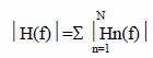
As an example simulated responses of filters based on an ordinary slanted transducer (plot 2) and QRST (plot 1) are shown in Fig.3.
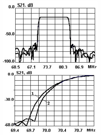
Fig 3 Comparison of simulation responses of quasirectangular (plot #1) and ordinary slanted filters
It should be mentioned that in comparison with a length of ordinary transducer Lor a length of QRST equals Lo » Lor *Fmin/Fmax , where Fmin and Fmax are minimal and maximal central frequency of sub-filters.
Experimental responses of the 77 MHz filter based on QRST are shown in Fig. 4. The filter is fabricated on 112o-LiTaO3 substrate. The first SPUDT transducer was unweighted and the second one was withdrawn weighted. The number of active layers was 25. The relative bandwidth of the filter was more than 15% and its shape factor for levels 40 dB and 3 dB is 1.17. A use of QRSTs allowed to reduce metal pattern.
Fig.4 Experimental responses of quasi-rectangular 77
MHz filter on 112o on LiTaO3 substrate
Usually tap weights for any given electrode of ST are the same for every channel across an aperture. Segmenting of an entire slanted filter into a discrete layer structure allows to synthesize these layers with different weighting functions. The frequency response of transition bandwidth regions is mainly determined by responses of sub-filters that are adjacent to respective edges of a transducer aperture. So channels closed to passband edge frequencies are more responsible for transition band and out-of-band rejection.
In order to improve a rejection withdrawal weighted transducer is usually used. Central layers mainly yield insertion loss (IL) of the slanted filter. If a filter length is fixed unweighted transducers can provide minimal IL.
A structure of such partially-weighted slanted transducer(PWST) that corresponds to the design
approach mentioned above is shown in Fig.5. The QRST has different weighting for central and lateral layers: lateral channels are withdrawal weighted but central ones are unweighted. Intermediate layers between lateral layers and unweighted ones are withdrawal weighted too but weighting functions for these layers are different. In order to provide straight electrical connections between fingers of adjacent layers the number of zero weights is decreased continuously from lateral layers to unweighted ones.
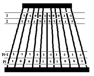
Fig.5 Transducer structure with partially weighted layers.
It should be mentioned that there are a few limitations for such PWSTs synthesis. These limitations are caused by requirement of electrical connections between layers.
- Positions of zero weights of an every layer which is closer to a transducer center have to coincide with corresponding zero-weights of a previous layer, i.e. a number of zero-weights of the layer can not be more than one for adjacent more faraway layers.
- Weight distributions of high frequency and low frequency layers are different, there is a shift by one weight between coincident layers.
A synthesis procedure was designed to simulate correct layer structures of partially weighted transducers. As initial data a number of unweighted and withdrawn weighted layers and weighing function of lateral layers are set. The synthesis algorithm provides weights simulation of every layer accounting limitation mentioned above. Besides optimization procedure is used in order to minimize out-of-band rejection.
Simulations show that IL of filters based on PWST are closer to unweighted transducers but better out-of-band rejection can be provided. Three responses corresponding to different slanted filter structure are shown in Fig.6. All filters have transducers of the same lenghts and SPUDT finger structure but have different weighting. 112o-LiTaO3 was used as a substrate.
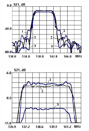
Fig.6 Frequency responses of slanted filter:
1 – filter based on unweighted transducers;
2 - filter based on partially-weighted transducers
3 – filter based on withdrawn-weighted transducers
Because numbers of non-zero weights are different for withdrawal weighted layers the correction of layer apertures is required to provide a desirable passband response.
As an example the distribution of layer apertures corresponding to partially-weighted filter is shown in Fig.7. Apertures of lateral layers exceed ones of central layers by 8-9 dB to provide a flat passband response. As the additional advantage of PWST may be mentioned that such distribution of apertures allows to decrease distortions caused by diffraction effects because of larger apertures of lateral layers.
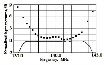
Fig.7 Distribution of layer apertures for partiallyweighted
filter
Experimental responses of the filter based on PWST are shown in Fig.8. The filter was used twosection slanted SPUDT transducers (finger pairs 1/16l- 3/16l). Withdrawal weighting of lateral layers correspond to Hamming functions. Their lengths were 150l and 89l. PWST include 8 withdrawal-weighted layers for each edge and 9 unweighted ones for the central part. The reflector distributions were the same for an every layer. The filter was performed on 112o-LiTaO3 substrate.
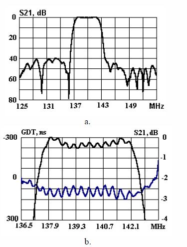
Fig.8 Experimental responses of partially-weighted
slanted filter on 112o LiTaO3 (insertion loss – 9.6 dB; 3
dB BW –5.2MHz):
a. - Out-of-band rejection
b. – Pass band responses
It should be mentioned that IL of the filter were improved more than 1 dB in comparison with a prototype.
Novel slanted transducer structures described above extend application abilities of slanted filters. The use of withdrawal weighting variation across an aperture yields smaller dimensions and IL in comparison with filter based on ordinary slanted transducers. The acceptable synthesis technique for such transducers and their modeling were developed. Experimental results for filters based on QRST and PWST well agree with simulations and confirm advantages of such filters for some applications. As the following step of a development such filters should be design an optimization algorithm for minimization of an out-ofband rejection.