The influence of parasitic surface transverse waves on responses of RSPUDT based filters is studied. Both experimental and simulated results show that parasitic STW generation deteriorates out-of-band rejection for RSPUDT filters on quartz substrate. Some filter structures providing partial reduction of STW distortions are considered. As a fundamental solution to the problem, a multi-mode synthesis is presented. This approach accounts for STW generation in the synthesis of RSPUDT. Experimental results well agree with filter simulations and high shape factor is achieved.
In the last a few years the interest for the use of resonant SPUDT (RSPUDT) for IF linear phase SAW filters has been growing [1,2]. Many IF filters, e.g., those used to select the channel in wireless communication systems, have narrow relative bandwidth allowing to use a low coupling substrate material like quartz. One of the main demands for these filters is the reduction of chip sizes. The reduction of die size can be achieved by increasing impulse response length with respect to the chip length. The RSPUDT filters combine the advantages of “classical” SPUDT filters and resonators including acoustical resonant cavities inside the SPUDT filter structures. Such structures are well suited for linear phase IF quartz filters with relative bandwidths up to about 2%. Such a structure enables reduction of die size by as much as 70% comparing to traditional in-line filters.
The successful implementation of RSPUDT requires the synthesis of transduction and reflection weighting functions for both transducers. The synthesis is a highly nonlinear optimization routine. Optimization algorithms were improved in recent years in order to account for secondary effects at the design stage. These effects become more and more important in order to reach better response and smaller die size.
Simple schematic of an in-line IF filter is shown in Fig.1. It includes two RSPUDTs and a central grating, which serves as the isolation shield for feedthrough signal suppression.

Fig.1 Schematic of an in-line RSPUDT filter
Transduction functions of the RSPUDTs are implemented as withdrawn weighted transducers (WWT) and resonant cavities introduced inside and between the transducers for the purpose of extending the impulse response of the filter. They correspond to alternate areas of positive and negative values of reflection weighting with local directivity in forward and backward directions. For internal SPUDT structures DART [3] and different-width split-finger (DWSF) reported by Hanma and Hunsinger [4] structures can be used. They have a shift between centers of reflection and transduction close to an optimal position in the transducer.
The design of an RSPUDT filter is based on the optimization routine reported in several papers [5,6]. The procedure provides an optimization of reflection and transduction functions of both transducers and the central grating simultaneously to minimize the weighted error of the filter transfer function with respect to the target response.
As an example of RSPUDT filter design the simulated and experimental responses of a 71MHz filter are shown in Fig.2. The comparison of these responses shows an obvious difference in rejection range.
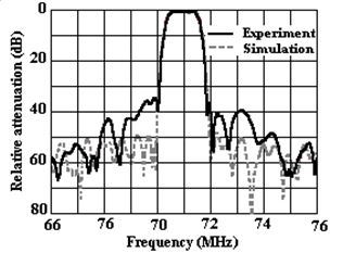
Fig.2 Experimental and simulated responses of a 71MHz RSPUDT filter
It should be mentioned that the sum of responses of separate transducers measured on a test wide band transducer is very close to simulated response of the RSPUDT filter.
In order to find out the reason of the difference a piece of acoustical absorber was placed on the acoustic path between transducers. The absorber width can be changed to provide attenuation variation. Amplitude responses of different attenuation levels are shown in Fig.3. As it follows from these plots, out-of-band rejection depends on SAW attenuation level much less than passband response. The experiment shows that the nature of the rejection response differs from SAW. The wide band response with the highest SAW attenuation is shown in Fig.4.
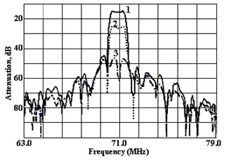
Fig.3 Measured responses of a 71 MHz RSPUDT filter with different attenuation levels between transducers
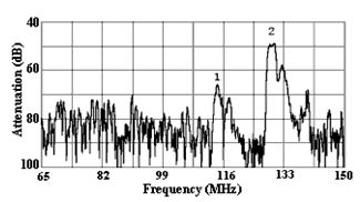
Fig.4 Response of an RSPUDT filter with suppressed SAW (absorber between transducers)
As it is seen from the response there are two parasitic passbands (marked as 1 and 2) corresponding to surface transverse waves (STW) [5]. Velocities of these STW are about 60% and 80% higher than that of SAW and they propagate below the surface of the substrate.
If these waves are accounted for during the RSPUDT filter analysis, the simulated result agrees with the experimental response much better. Measured and simulated responses of the 71MHz filter with parasitic mode generation accounted for are shown in Fig.5.
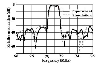
Fig.5 Comparison between experimental response (black plot) and simulation result (STW are accounted)
The experiment and analysis results show that STW can deteriorate the rejection in RSPUDT filters much more than what designed for. Frequency ranges of the STW generation that distorts the response of a RSPUDT filter near its central frequency are much lower than the central frequency. These frequency ranges are determined by the ratio of STW and SAW velocities.
Normally the RSPUDT filter synthesis is accomplished for a limited frequency range near the central frequency of the filter and STW generation ranges are not controlled. For withdrawal weighted structure of RSPUDT, side lobe levels in these ranges can be much higher than rejection requirements of the synthesized filter. The problem is particularly important for filters with sharp transition bands. The design goal is to suppress and/or account for these parasitic waves under synthesis procedure in order to reach the required rejection.
In order to improve RSPUDT filter responses simulation and structural approaches can be used.
Structural methods are based on STW suppression by means of special transducer structures. As an example a double-track filter is shown in Fig.6. It comprises twoidentical tracks. But distances between transducers are shifted by a value d. The shift is selected to provide the minimal distortion for SAW response and maximal suppression for STW responses.
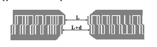
Fig.6 Double-track filter structure for STW compensation
Simulated responses of single track and double track with d=0.9lo (lo - is the SAW wavelength at central frequency) are shown in Fig.7. The comparison between these two responses shows that a double-track structure provides about 10 to 15dB rejection improvement due to STW compensation.
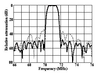
Fig.7 Simulated responses of double-track (solid) and single-track (dashed) filters
The second approach is to use an apodized and an unapodized transducer for the RSPUDT filter. In this case the responses of the transducers provide much better STW suppression. As an example the simulated response of two matched RSPUDT filters based on the same transduction and reflection weighting functions are shown in Fig.8. The first filter is made with two withdrawn weighted (WW) RSPUDTs, and the second filter consists of one WW SPUDT and an apodized RSPUDT. As these responses show, out-of-band rejection in the ranges of STW generation is improved by about 20 to 25dB with the introduction of the apodized RSPUDT.
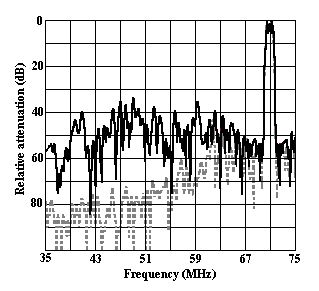
Fig.8 Simulated responses of unmatched filters:
dashed plot – the filter with an apodized and WW RSPUDTs;solid plot – the filter with two WW RSPUDTs
The suppression methods shown above have some disadvantages due to diffraction distortions. In our opinion the most effective method to achieve better rejection in RSPUDT filter design is the so-called multi-mode synthesis. This method is based on the synthesis routine including both SAW and STW in the synthesis of the filter response. In this case STW not only are accounted for during synthesis but also can be used to improve the rejection comparing to the “pure” SAW synthesis procedure.
The procedure of the multi-mode synthesis of an RSPUDT filter is identical to the ordinary synthesis routine including the followings:
-change of transduction and reflection functions within a limited number of optimized transducer samples;
-analysis of new RSPUDT configuration accounting for second order effects;
-simulation of a weighted multi-criteria error between the actual and the target transfer functions;
The cycle is reiterated for all allowed combinations of transduction and reflection weights.
The procedure is repeated for each STW and SAW modes and frequency responses are added up. The structure corresponding to the minimal error is chosen.
The equivalent circuit model is used for the analysis of frequency responses. Substrate and propagation parameters are set for each mode before the simulation. But some options such as simulation of topology, charge distribution etc. are common for all modes, which allow to reduce the simulation time for an actual filter design.
The multi-mode synthesis algorithm was used to design the 71 MHz RSPUDT filter. Two filter variants were designed. The first filter was based on DART SPUDT structure, the second on DWSF structure.
The shape factor is less than 2:1 at 40 dB with a typical –1 dB bandwidth of 1.1 MHz. The filters were assembled in the standard 13.3 x 6.5 mm2 SMT package. Measured responses of matched filters are shown in Fig.9 and Fig.10, respectively. Simulated responses with STW generation accounted for are shown as dashed plots.
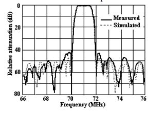
Fig.9 Responses of simulated and measured DART RSPUDT filter (Insertion loss 14.0dB)
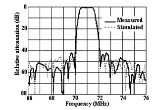
Fig.10 Responses of simulated and measured DWSF RSPUDT filter (Insertion loss 10.4dB)
These performances are obtained on a single ended 50 ohm source and load impedances with a serial inductance and a parallel capacity matching component at each port. Amplitude ripples are about 0.5dB and group delay variation is about 200ns in the passband.
Insertion loss is about 14.0 dB for the filter based on DART structure and 10.4 dB for the DWSF. The difference between insertion loss is caused by different locations of transduction weights for these SPUDT structures. The efficiency of SAW generation for DWSF SPUDT is higher but reflection per wavelength is lower comparing to DART. The choice of SPUDT structure for a filter design depends on the filter specifications.
A new approach to RSPUDT filter design has been presented. It accounts for the STW generation in the filter synthesis. The multi-mode synthesis routine allows to improve the filter out-of-band rejection by 3 to 5dB and achieve better shape factor comparing to the traditional synthesis routines. The synthesis algorithm was developed. Experimental responses of RSPUDT filters on quartz substrates were shown with good agreement with simulated results of DART and DWSF SPUDT structures.