This paper describes SAW filters based on quasi-slanted transducers. Stepped electrodes structures used for such filters realization provide decreasing of filter shape factor and simplify their performance. Experimental results of the filters with relative bandwidths from 2 % to 70 % are represented.
SAW filters based on slanted or tapered transducers have been under extensive development in recent years [1-4]. The implementation of the slanted unidirectional transducers allows the insertion loss reduction and the triple-transit signal suppression in a wider frequency band as compared with transversal filters. Because of this, the slanted transducer SAW filters find a widespread application as key components in modern wide-band mobile communication systems.
Slanted SPUDTs can be thought of as a set of parallel acoustic channels or comparatively narrow-band sub-filters. The relationship between the amplitude and phase of the reflected and excited SAW in each acoustic channel can be brought closer to the optimal one for the substrate material and the type of SPUDT in use.
However, the implementation of the electrodes with varying width and period complicates the design of slanted SPUDT filters. For example, a filter responses become strongly diffraction-dependent and it is difficult to make a filter matching. All this become still more complicated for low shape factor filters SH=1.2¸1.4 because the number of electrodes is increased.
In this paper so-called quasi-slanted transducers (QST) with stepped electrodes and design methods of filters with SH=1.2¸1.4 on the basis of these transducers are described. In some cases, the quasi-slanted transducers allow better filter parameters and a wider use of such filters.
For convenience sake slanted transducers and filter are considered as a set of parallel channels having constant periods along SAW propagation axis. The number of channels for the analysis of a filter depends on its relative passband width BW and commonly is MC=50¸100. Central channel frequencies fi can be determined as fi = fi-1×(1+a)/(1-a), where a=BW/N, N is the number of electrode pairs in a channel.
At the above nonuniform distribution of fi the magnitude of amplitude ripples in the passband depends on a relative passband width of a filter [4] (Fig. 1, plot 1).
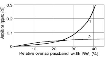
Fig.1. Relationships between amplitude ripples in passband and relative passband width: nonuniform (1) and uniform (2) frequency distribution.
In the case of uniform distribution of the channel frequencies fi = fi- 1 +df , where df =(fmax - fmin)/(MC -1), an amplitude of ripples hardly depend on the passband width (Fig. 1, plot 2). Here fmax and fmin are the maximum and minimum channel frequencies of the passband respectively.
A slope of the amplitude response arising at the frequency distribution indicated is easy to be compensated by adjusting the apertures of sub-filters.
Referring to computations, the greater the number of channels in a slanted transducer, the narrower the passband width. As an example, Fig. 2 shows the relative transition bandwidth (TBW) and the passband amplitude ripples Da as functions of the number of channels MC for a filter with the relative passband width BW=20%.
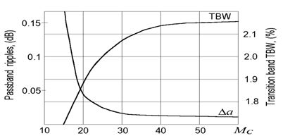
Fig.2. Relation ships of transition bandwidth (TBW) and passband ripples ( ) on channel number ( =60 pairs).
From Fig. 2 one sees that the transition-band width can be decreased about by 15% at amplitude ripples not exceeding 0.1 dB and comparatively small number of channels, MC =10¸30.
For the filters with the small number of acoustic channels MC =10¸30, the electrode shape of slanted transducers approaches the stepped one, as shown in Fig. 3b. Unlike slanted transducers with continually varying electrode width and period (Fig.3a) these transducers can be called quasi-slanted (QST).
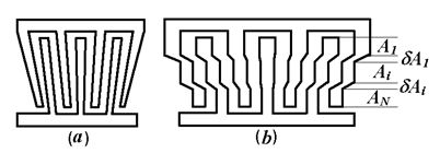
Fig.3. Electrode shape of conventional slanted IDT (a) and quasi-slanted IDT (b).
QST is a set of parallel acoustic channels, each of which has a uniform electrode width, period, and aperture A i in the direction of SAW propagation. The like straight electrodes in the adjacent channels are electrically connected in equipotential stepped electrodes using connection layers with the apertures dAi (Fig. 3b). The computation yields that if the ratio dAi /Ai <15¸20, then the effect of connection layers on the frequency responses of the filter can be disregarded.
As was mentioned above diffraction effects and SAW flow beam deviation still considerably distort characteristics of slanted transducers based filters. Fig. 4 shows the experimental amplitude response for two structurally identical filters with the different transducer apertures W1=80l and W2=120l . At the insufficient filter aperture, W1=80l, the characteristic distortions are the appearance of pronounced amplitude ripples near the low-frequency limit of the passband, the narrowing of the passband, and the broadening of the high-frequency transition band of the filter. The above distortions of the amplitude response arise owing to the SAW beam steering and diffraction. To one or another degree they are typical for all substrate materials (quartz, lithium niobate, lithium tantalate). These effects primarily show up in the filters with the low shape factor SH=1.2¸1.4, where the mean slope of the edge electrodes of slanted transducers must be far more greater than the slope in the transducers having the same passband but worse shape factor SH=1.5¸2.5.
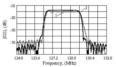
Fig.4. Comparison of responses two identical slanted filters with different apertures: 1- W1=80l; 2-W2=120l.
Increasing of an aperture of slanted and quasi-slanted transducers decreases distortions. However, with the increase in an aperture , the transducer capacity CT also proportionally increases and the radiation resistance Ra decreases, complicating filter-load matching. To solve the problem transducers with serial-connected electrode sections[5] are commonly used (see fig.5). The multi-section transducers decrease CT by a factor ps2 (ps is the number of sections) and increase the input impedance of the filter. The implementation of such multi-section transducers allows the optimization of their equivalent aperture in order to minimize amplitude ripples and insertion loss of quasi-slanted SPUDT filters.
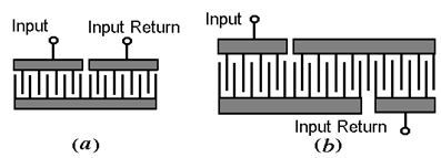
Fig.5. Structures of multi-section transducers: a – two-section IDT; b – three-section IDT.
To analyze QST filters, a modified equivalent circuit model [6] has been used. This model takes into account second-order effects and fairly accurately describes the filter characteristics with due regard for loads and matching circuits.
Withdrawal weighted transducers were used in order to achieve the needed filter selectivity [2]. In this case, we employed an optimization procedure that provides the maximum rejection in the stop-band at the fixed transducer lengths.
To obtain the desired amplitude and phase responses we corrected the channel apertures and channel positions in the direction of SAW propagation.
A performance of slanted electrodes with varying width is the difficult stage in the fabrication of conventional slanted SPUDT filters. The slanted electrodes are divided along their aperture into 500¸1000 fragments. As a result, the number of flashes and, hence, the production time abruptly increase.
The use of quasi-slanted SPUDT substantially simplifies the photomask fabrication. In this case, the main problem is the creation of connection layers. The layout of these layers may be different (Fig. 6).
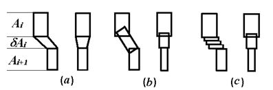
Fig.6. Variants of connection layers performance: a – trapezoid; b – slanted rectangles, c – rectangles.
If the elements of connection layers are alike and have the form of a trapezoid (Fig. 7a) or rectangle (Fig. 7b), the number of flashes during the photomask production is considerably reduced.
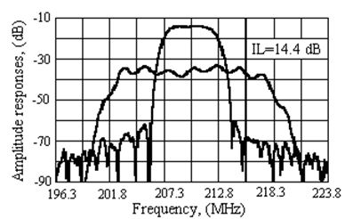
Fig. 7. Frequency responses of 210 MHz filter on ST-quartz
(in passband - 0.5 dB/Div and 0.6 MHz/Div).
In the case that these layers are of the form of parallel rectangles, the total number of flashes is also substantially reduced providing an optimization procedure is used. This procedure minimizes the required number of flashes, depending on a the pre-set overlap of adjacent layers.
Thus, the total number of flashes during the fabrication of the photomask for QST filters can be reduced by a factor of 3¸10 as compared with the conventional slanted SPUDT.
4. EXPERIMENTAL RESULTS
Several QST filters with different relative passband widths in the range 2-70% have been designed for mobile, wireless, and satellite communication systems.
Two narrow-band 210 MHz filters with the passband width BW3=4.5 MHz (or 2.1%), and SH»1.5 have been fabricated on the ST-cut quartz and XYs/1120-cut lithium tantalate substrates. Both the filters involve per 9 sub-filters with one withdrawal weighted DART SPUDT and one bi-directional transducer.
The aperture of the quartz filter was 500 mm . The input and output transducers used two series-connected electrode sections L1=120l and L2=140l long (Fig. 5a).
The aperture of the filter on LiTaO3 was 650mm, by L1=140l and L2=180l. Each of the transducers involved three series-connected electrode sections.
The frequency responses of the filters are depicted in Fig. 7 and Fig. 8, respectively.
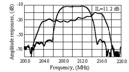
Fig. 8. Frequency responses of 210 MHz filter on XYs/112o LITaO3 (in passband - 0.5 dB/Div and 0.6 MHz/Div).
Resistive loss of the filter on LiTaO3 were higher, because the number of series-connected electrode sections was greater. However, insertion loss of this filter (IL=11.2 dB) were 3 dB less than those of the quartz filter (IL=14.4 dB). Both the filters were housed in SMD 9.0x7.0x1.6 mm packages.
The frequency responses of the middle-band 280 MHz filter with the passband BW3=20.5 MHz (or »7%) are shown in Fig. 9. The filter involved two withdrawal weighted TES SPUDTs [7]. Insertion loss were IL=7.7 dB and SH(40/3)=1.4. The YZl-cut LiNbO3 substrate has been used. The filter package was SMD 5.0x5.0x1.2 mm.
The wide-band 75 MHz filter with the passband BW3=15 MHz (or 20%) involved two quasi-slanted NCF SPUDTs [8] L1=53l and L2=61llong. The transducers used the block weighting of electrode sections [4]. Fig. 10 shows the frequency responses of the 75 MHz filter. The insertion loss were IL=10.8 dB and shape factor was SH(40/3)=1.3. SMD 13.3x6.5x1.6 mm package have been used.
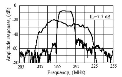
Fig.9. Frequency responses of 280 MHz filter on YZl-LiNbO3 (in passband - 0.5 dB/Div and 3.0 MHz/Div).
The frequency responses of the extra wide-band 350 MHz filter with the passband BW3=250 MHz (or 70%) are shown in Fig. 11. Two unweighted bi-directional QST L1 =20l and L2 =30l in length have been used. The filter had untuned insertion loss IL=34.4 dB and the shape-factor SH(30/3)=1.08; passband amplitude ripples were less than 1.0 dB. The YZ-cut LiNbO3 substrate has been mounted in the SIP-4M package.
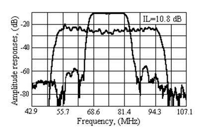
Fig.10. Frequency responses of 75 MHz filter on YZl-LiNbO3 (in passband - 0.5 dB/Div and 2.0 MHz/Div).
This paper reports on the results of the development of the QST SAW filters. To achieve the pre-set frequency responses, QST use the minimum number of acoustic channels MC=10¸30 with shifted frequencies of synchronism. The method makes it possible to reduce die sizes of filter by 10-15% or to improve the shape factors if the die sizes are fixed.
The experimental data obtained for the filters made on different substrates indicate that QST can be widely used to improve the filter parameters and facilitate the fabrication of photomasks.
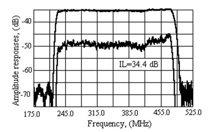
Fig.11. Frequency responses of 350 MHz on YZl-LiNbO3 filter (in passband - 1.0 dB/Div and 35 MHz/Div).
[1] H.Yasuda and K. Yamanouchi, "Automatic Computer-Aided Design of Slanted Finger SAW Filters Using a Building-Block Method", IEEE 1998 Ultrason. Symp. Proc.,1998, pp.239-242.
[2] E.V.Bausk, I.V.Yakovkin, "Withdrawal Weighted Fan-Shaped SAW Transducers", IEEE Trans. Ultrason., Ferroelect., Freq. Contr., vol. UFFC-42, No 1, Jan. 1996., pp.164-169.
[3] L. Solie, "Tapered Transducers – Design and Application", IEEE 1998 Ultrason. Symp. Proc., pp.27-37.
[4] H. Yatsuda, "Design Technique for Nonlinear Phase SAW Filters Using Slanted Finger Interdigital Transducers", IEEE Trans. Ultrason., Ferroelect., Freq. Contr., vol. UFFC-45, No 1, January 1998., pp.41-47.
[5] A.Y.Dryahlov, "Ultrasound Delay Line on SAW", Russian Patent No 716139, Int. Cl3 HO3H 9/42, dated May 5, 1977.
[6] K. Inagawa and M.Koshiba, "Equivalent Networks for Interdigital Transducers”, IEEE Trans. Ultrason., Ferroelect., Freq. Contr., vol. UFFC-41, No 3, March 1994, pp. 402-411.
[7] V.B.Chvets, P.G.Ivanov, V.M.Makarov, V.S.Orlov, “Low-Loss Filters Using New SPUDT Structures”, IEEE 1997 Ultrason. Symp. Proc., pp.69-72
[8] B.Hunsinger et. al, "Surface Acoustic Wave Device with Reflection Suppression", Patent of USA, No 4162465, Int Cl2 HO3H 9/04, dated July 24, 1979.