The new SPUDT structures based on triple electrode sections (TES) per wavelength with the period between SAW sources about nl/3 are presented. The simulation technique which accounts for second order effects has been developed within the framework of modified equivalent circuit model. The SPUDT structures have been implemented in filters with 0.1-3.2% bandwidths fabricated on quartz and LiTaO3 substrates.The results of simulation have been verified experimentally and show that insertion loss of TES SPUDT filters is less by 1.0-1.5 dB than that in conventional SPUDT filters. The impedance frequency dependence becomes more symmetrical and the passband distortions are reduced. Stopband rejection is 50-60 dB.
SAW low-loss filters based on single phase unidirectional transducers (SPUDT) are widely used in telecommunication systems such as mobile telephone, cordless phone and systems with frequency division multiplexing (FDM). The main requirements for SAW filters in these applications are high selectivity for spurious signal suppression, low insertion loss for decreasing of power consumption, low phase deviation in passband and high shape factor (SF) for reducing signal distortion and small chip and package size for low cost.
SPUDT filters employ a single metal layer fabrication that is important for the mass production. The most widely used SPUDT structures are DART [1] and EWC [2]. Both include one/two l/8 exciting electrodes per a wavelength (l is a wavelength at a center frequency) with l/4 pitch between them and acoustic reflectors of l/4 (EWC) or 3l/8 width (DART).
In addition to certain advantages these structures exhibit some drawbacks. First of all, small electrode size (l/8) complicates a fabrication and limits upper range of filter operating frequencies. Second, the distance between SAW sources in DART and EWC, which is about l/4, does not correspond to optimum l/2 distance used in bidirectional IDTs. As a result, SAW generation efficiency in mentioned SPUDTs is only 0.448-0.528 of that for bidirectional IDTs[3]. Therefore, insertion loss is rather high for middle passband SPUDT filters [4].
Third, if a filter bandwidth corresponds to selfmatched case, passband distortion is usually observed caused by the reactive part of the transducer impedance.This effect degrades frequency responses of passband filters, especially with high shape factor SF=1.5-1.7.
The SPUDT efficiency can be increased in two ways: the first one is optimum arrangement of SAW sources within a transducer period and the second one is the use of materials with high electromechanical coupling coefficient.
In the present paper, the new SPUDT structures are described which are partially free of drawbacks typical for EWC and DART. These structures are based on IDTs with nl/3 period of sources [5]. In such structures, compensation of spurious reflections from electrodes occurs within periodical groups of three l/3 or l/6-widthelectrodes. In the first TES SPUDT structure, the groups of three sources and internal reflectors providing unidirectional behavior are spaced apart. In the second structure, the reflectors are combined with SAW sources.
To optimize positions and widths of sources andreflectors within transducer, the accurate models are required accounting for second order effects, substrate properties and metal film thickness. The structures have been optimized using equivalent circuit model.
In order to realize unidirectionality in TES SPUDT, two different structures have been used. The first one is a group type structure. The reflectors are located between conventional TES with l/6 electrodes (Fig.1). If the minimum gap sizes are limited, the period between TESs may be given as Lp=kl/2 where k=4,5,6 etc. The maximum number of reflectors in each gap is (k-3).
The relative efficiency of SAW generation and reflection per wavelength is somewhat less than in DART and EWC because of sectionalization. However, these transducers can be successfully used in narrowband and high-frequency filters when the number of sources and reflectors is surplus.

Fig.1 Group type TES SPUDT construction.
Another way to provide unidirectionality is an utilization of TES for generation and reflection of SAWsimultaneously similar to conventional SPUDT structures.
This new TES SPUDT is schematically shown in Fig.2a. The length of elementary section is l. It comprises three electrodes with different widths and non-symmetrical positions within the section.
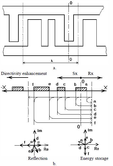
Fig.2 The construction (a) and mechanism providing unidirictionality (b) in TES SPUDT.
The simulation of the charge distribution under electrodes in such TES reveals that normalized static capacitance and normalized conductivity of a new TES SPUDT coincide with similar parameters of a bidirectional TES transducer. Due to asymmetry, the phase shift of the excitation center referred to the center of electrode is about 5o. The simulation shows that the efficiency of SAW generation in the new TES SPUDT structure is higher by approximately 30% than in EWC.
The mechanism of unidirectionality in TES SPUDT is explained in the diagram (Fig.2b) showing there flections from electrode edges and vector diagrams of partial waves. As it follows from diagram, the wave amplitude in +X direction:
![]()
while for waves propagating in -X direction an amplitude is:
![]()
where E is SAW amplitude, r is reflection coefficient at electrode edges.
The SAW energy storage effect essentially effects the unidirectional behavior of TES SPUDT. For thin metal films (h/l=0.1-0.5%) on quartz substrates, a real component of normalized reflection coefficient per wavelength is less by 40% than in DART structure and about twice less than that of EWC. While using thick metal films (h/l=1-4%), the reflection coefficient is essentially increased due to energy storage effect [6]. Components of reflected waves corresponding to energy storage effect are shown in Fig.2b. It can be concluded that this reflection component is:
![]()
where B is energy storage coefficient. Summarizing of equations (2) and (3) gives:
![]()
Thus the energy storage effect increases SAW directivity in TES SPUDT if a quartz substrate is used. An analysis of results obtained in [7] and our experiments have shown that for ST-quartz substrates and for an aluminum film, r(h/l)»0,27(h/l) and B»30(h/l)2. It also follows from (4) that real component of reflection coefficient is equal to that in EWC structure if metal film thickness h/l»1.8 %.
It should be mentioned that the conventional TES structure (all fingers of l/6 width) is used if a local transducer reflectivity has to be zero for a filter design.
As an example, S21 frequency response of a resonant SPUDT filter based on group type TES is shown in Fig.3. It comprises two withdrawal weighted TES SPUDTs. . Inorder to suppress spurious frequency responses caused by sectionalization, the first transducer has section period Lp=2l and the other one 2.5l. This filter was fabricated on ST-quartz substrate with dimensions 15x2x0.5 mm. Filter bandwidth is 150 kHz and the insertion loss is -5.2 dB at the center frequency f0=180 MHz. An ultimate rejection within the frequency interval (f0 ±0.7% ) exceeds 50 dB.
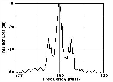
Fig.3 Experimental response of group type TES SPUDT filter.
In order to verify the practical usefulness of TES SPUDT structure and for a comparison with conventional SPUDT based structures, several filters for mobile radio applications were designed.
The synthesis procedure for calculation of weighting coefficients for TES SPUDT is based on frequency tap method described in [8]. A synthesis of reflection weighting function and optimization of film thickness and widths was carried out using an iteration procedure based on the equivalent circuit model. In filter analysis the following second order effects were taken into account:charge distribution under electrodes, resistive loss, SAW propagation loss, reflection and energy storage effects.
Filters were fabricated on ST-quartz and 112o LiTaO3 substrates. The matching components have been optimized to realize minimum passband ripples in both amplitude and group delay responses.
The simulated and experimental S21 frequency responses of filters for DECT system based on TES SPUDT are shown in Fig.4. Two filter structures were compared. Similar weighting coefficients were used in both filters but the first filter consists of two withdrawal weighted (WW) transducers of DART structure, and the second one comprises two WW-TES SPUDT. Both filters were fabricated on ST-quartz substrate, chip dimensions are 6.5x3.0x0.5 mm. Aluminum film thickness is 4000 A.
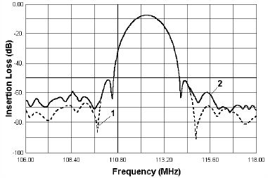
Fig.4 Simulated (1) and experimental (2) responses S21 of TES SPUDT filter for DECT.
The frequency responses of both filters are almost similar. Bandwidths at 3 and 40 dB levels are 1.18MHz and 3.45 MHz respectively, i.e. SF=2.9. Stopband level is 45-46 dB, ultimate rejection is better than 55 dB. The insertion loss is 8.95 dB for DART and 7.5 dB for TES SPUDT, i.e. the gain is 1.45 dB.
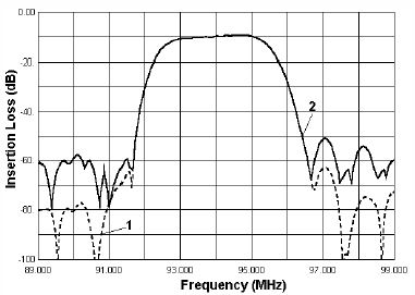
Fig.5 Simulated (1) and experimental (2) responses S21 of DART filter for system with FDM.
As it was mentioned above, the design of low-loss filters with SF£2 is the actual task. The simulated and experimental frequency responses (S21) of such filters designed for systems with frequency division multiplexing are shown in Fig.5 (DART SPUDT) and Fig.6 (TES SPUDT). The same weighting coefficients were used in both filters. The filters comprise WW and overlap SPUDTs. Both filters were produced on 112o- LiTaO3, the chip dimensions are 12.5x2.5x0.5 mm, the aperture is 0.6 mm, and film thickness about 9000 A.
Both filters have approximately the same bandwidth(about 2.56 MHz or 2.72%) and stopband rejection level of 45 dB. The shape factors are about 1.6. But the filter based on TES SPUDT exhibits lower insertion loss: (8.3 dB) compared to DART filter (9.5 dB).

Fig.6 Simulated (1) and experimental (2) responses S21
of DART filter for system with FDM.

Fig.7 Simulated conductivity responses (1-DART, 2-TES) of filters for systems with FDM.
Besides, the passband distortions in TES SPUDTfilter are less by 1 dB than those in DART. The difference between passband magnitudes is caused by different behavior of SPUDT impedances. The frequency dependencies of Ga(f) for DART (plot 1) and TES SPUDT (plot 2) are shown in Fig.7. It can be seen that the conductivity is larger and the symmetry of plot is better for TES structure.
The new group type SPUDT based on 3/l-period TES is described. Such structures can be used in low loss filters with BW=0.05-0.2% and stopband rejection more than 60 dB.
The new TES SPUDT with asymmetrical electrode arrangement provides better efficiency of SAW generation than DART or EWC SPUDT. It allows to decrease the insertion loss by 1.3-1.5 dB in SPUDT based filters. Such transducers can be used in filters with bandwidth about 1-3% on quartz or 2-5% on LiTaO3 substrates. Besides, the use of TES SPUDT permits to decrease passband distortions in filters with required high selectivity (SF=1.5-1.8).