One way to improve the performance of SAW devices is to use new piezoelectric materials that have advantages in certain electro-mechanical properties. A special session of the last Ultrasonics Symposium (SU-98, Japan, October 5-8, 1998) was devoted to LGS properties and devices. Recently, lithium tetraborate (Li2B4O7) substrates have drawn attention of SAW designers.
Lithium tetraborate (LBO) has the electro-mechanical coupling coefficient (k2) larger than that of quartz for SAW. In some SAW propagation directions on certain cuts of LBO crystal, the first-order temperature coefficient is zero[1-2]. These crystal cuts are attractive for IF filter applications. Due to these properties LBO is a promising substrate for low-loss and small size SAW filters, especially based on resonant and RSPUDT structures. Small-size low loss SAW filters on LBO were presented [3,4].
In this paper small-size low-loss filters on LBO using longitudinally-coupled resonators (LCR) and single-phase unidirectional transducers (SPUDT) are described. Experimental investigations were focused on substrate properties that are significant for SAW applications (k2, SAW velocity, reflectivity and energy storage ratios). These parameters were used for modeling SAW filters based on LBO substrates.
Two filter types were designed. The first is a 71 MHz 4-pole LCR filter for GSM-IF application. The filter has insertion loss (IL) about 3.0 dB and is mounted into a 9x7 mm SMD package. The second is an 83 MHz CDMA filter was designed as 3-track structure based on SPUDT. IL of the filter is 6.3 dB. Lengths of SPUDTs are only 60 wavelengths to provide required frequency responses. In comparison with identical filters on quartz substrates filter on LBO have better IL and smaller die sizes.
One of widely used LBO wafer orientations is Euler angle (45o, 90o, 90o), commonly known as 45o X-Z cut. TCD is 0ppm/oC near the room temperature for this cut. The coupling coefficient k2 of this cut is about 1% that is about 8 times larger than that of ST quartz. Besides, the reflection coefficient of LBO is more than 3 times higher than that of quartz [3]. These substrate properties suggest that filters based on LBO are possible to achieve better IL and wider bandwidths and/or smaller dice sizes for the same parameters comparing to quartz filters.
But for adequate modeling and correct design of SAW filters additional substrate parameters and dependencies should be known. One of such parameters is the energy storage coefficient Se that determines not only SAW velocity change but also effective reflection from metal strips depending on their widths.
In order to detect substrate properties and their dependence on relative thickness of metal film (h/l - where h is film thickness, l is a wavelength), the test structure with four acoustic tracks was used (Fig.1). Every track comprises two IDTs with split fingers. For two tracks (1 and 2) single-finger IDTs (150 finger pairs) were placed between transducers The transducers had different metallization ratios (MR=a/d where a is a finger width; d is transducer pitch) MR1=0.75; MR2=0.5. The metal bar of the same length was placed into the third track. The last track had no element between the two IDTs.
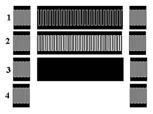
Fig.1 Test structure for a measurement of substrate parameters
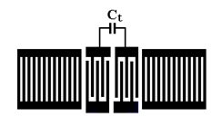
Fig.2 Structure of double-mode LCR unit
Comparison of measurement results corresponding to different tracks and metal thickness allows to estimate main parameters of substrate and their dependence on h/l.
Dependencies of reflection and storage energy coefficients per a single metal edge, determined from experimental responses, can be represented as:
R = Ro + R1 (h/l) + R2(h/l)2 ;
Se = So + S1 (h/l) + S2(h/l)2;
where Ro=0.0019; R1 =1.3; R2 =0; S0 =0; S1 =0; S2 =220.
The analysis of Ri and Si shows that SAW reflections and storage energy effects depend on film thickness much more than corresponding coefficients for quartz substrate. For example R1 is about 3.5 times and S2 is about 7 times larger than those of quartz.
SAW devices on LBO were fabricated through contact printing photolithography method. Because LBO substrates can dissolve in acid and water, the surface of the substrate was protected with SiO2 layer before the fabrication process started and alkali etching process was used [5,6].
SiO2 and Al films were deposited by sputtering method. The thickness of SiO2 layer was about 200A. Such layer (h/l»0.04%) provides a protection of the substrate surface and reduces k2 by 0.1% [3]. Thickness of Al varied from 0.1 mm to 1.0 mm.
Two filter structures on LBO substrates were designed.
The first filter is a 4-pole double-mode LCR structure [7]. In order to meet GSM specification double-mode type was used. The single resonator (Fig.2) includes two IDTs (51 and 91 fingers) and lateral grating (50 strips). The resonator aperture was 10l. In order to achieve maximal reflection from strips MR was 0.75 for IDTs and gratings. The pitch ratio between transducers and gratings was 0.99.
In order to obtain steeper transition band additional capacity Ct was completed as topological element of the resonator. The influence of Ct on the filter responses is shown in Fig.3
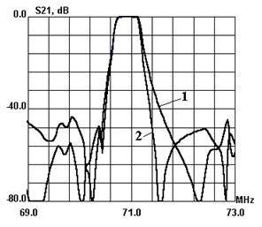
Fig.3 Influence of transition capacity between transducers on LCR filter responses: 1 – Ct=0; 2 – Ct=0.2 pF
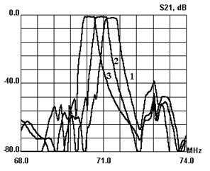
Fig.4 Simulated responses of LCR filter for different thickness of Al film: 1 - 0.4 m; plot 2 - 0.5 m; 3 - 0.6 m
The equivalent circuit model was applied for the filter simulation. LBO substrate parameters that were determined experimentally were used. Simulated responses for different thickness of Al film are shown in Fig.4. As shown from these plots the center frequency of a filter on LBO depends greatly on metal thickness variation.
One of the main problems of resonant filter design was the suppression of spurious modes. In order to weaken higher longitudinal modes special finger structures and withdrawn IDTs were used. But efficiencies of such transducers are less than that of an ordinary IDT with single (l/4) fingers.
The other approach was used for the filter design. Amplitudes of spurious modes can be reduced if parameters of single resonators (resonant cavity, aperture etc) are a little different. As an example experimental responses of filters with identical and different apertures are shown in Fig.5. As shown from the responses 10% variation of apertures between resonators allows to weaken higher transversal modes.
Comparison of simulated and experimental responses is shown in Fig.6. Experimental responses agree with simulation results very well.
Experimental responses of the 71 MHz GSM-IF filter are shown in Fig.7. Al thickness for this filter was 0.5 mm. Metal pattern dimensions were 5.8 x 2.1 mm. It was mounted in hermetic 9x7mm SMT and SIP-4M packages. The filter has about 3.0 dB IL and out- of-band rejection is higher than 45 dB. 3dB bandwidth is 390 kHz and provides required temperature and fabrication tolerance. Out-of-band rejection is more than 40 dB at fo+/-400 kHz.
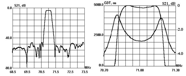
Fig.5 Comparison of experimental responses: 1 – identical 2-pole LCR resonators; 2 - resonators with different apertures
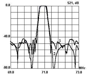
Fig.6 Comparison of experimental (1) and simulated (2) responses
Fig.7 Experimental responses of 71 MHz GSM-IF filter
The second filter on LBO substrate is an 84 MHz multi-track SPUDT filter [8]. The filter structure is shown in Fig.8. It comprises three identical SPUDT filters connected in parallel. Distances between transducers differ by lo/3 (lo is wavelength at center frequency) to suppress main SAW signal. Under this condition a triple-transit signal is used to achieve the desired response.
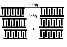
Fig.8 Structure of 3-track filter
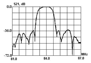
Fig.9 Experimental response of 3-track filter
Lengths of withdrawn weighted SPUDTs are 60 wavelengths. Apertures of partial filters are 11l. Al thickness is 0.45 mm. Metal pattern dimensions are 5.5 x 2.4 mm.
Experimental response of the 3-track filter is shown in Fig.9. IL of the filter is 6.5dB, 3 dB bandwidth is 1.2 MHz and bandwidth for 30 dB level is 1.74 MHz.
Basing on experimental parameters of 45-X LBO substrate fine tuning of the model and design of SAW filters on LBO were completed. Al/SiO2 layered structure and contact printing photolithography method were used for test devices and filters fabrication.
The 71 MHz GSM-IF filter was designed as a 4-pole LCR structure. It included additional capacity between transducers to reduce transition band. Performance of double-mode resonators with different apertures allowed to reduce spurious modes. The filter achieved insertion loss about 3.0dB. 3 dB bandwidth was 390 kHz and shape factor from 40 dB to 3 dB was about 2. Dice sizes of the filter were about 6.4 x 2.3 mm.
The 84 MHz filter was designed as 3-track structure to reduce filter dimensions. It provides IL about 6.5 dB and 3 dB bandwidth about 1.2 MHz. Die sizes of the filter were about 6.4 x 2.3 mm.
[1] Y.Ebata and M Koshino, Jpn Appl.Phys.26-1, 1987, p.123
[2] .H. Abe, M. Ohmura & H. Saitou, "SAW devices on lithium tetraborate (Li2B4O7)", IEEE Freq. Ctrl. Symp., pp. 289-295, 1994.
[3] S. Ichikawa, Y. Ebata, M. Koshino, N Mishima, “Small-sized 71 MHz GSM-IF filter using SAW resonator on Li2B4O7 substrate”, Proc. 1998 IEEE Ultrasonic Symp. Proc., pp. 43-46
[4] S. Ichikawa, S. Mitobe, M. Koshino, Y. Ebata, "A low-loss CDMA-IF filter based on RSPUDT on LBO substrate", 1999 IEEE Ultrasonic Symp. Proc, pp. 351-356
[5] M.Ohmura, et. al. 1990 IEEE Ultrasonic Symp. Proc., pp. 135-138
[6] S. Matsumura, et.al. 1990 IEEE Ultrasonic Symp. Proc., pp. 247-250
[7]. T. Morita, et. al. "Low loss double mode SAW filters", 1992 Ultrasonics Symp. Proc., pp. 95 -104.
[8] R.Dill, J. Machui and G.Muller " A novel SAW filters for IF-filtering in DECT systems", IEEE Ultrason. Symp. Proc., pp. 51-54, 1995.